F.A.Q
-
Measuring angles with rotary encodersPulse (PPR) square wave, also known as rectangular wave.
■ Number of output pulses / revolution (PPR) The number of pulses output by one revolution of the rotary encoder is usually the same as the number of grooves of the encoder inside the rotary encoder for an optical rotary encoder (the output pulse The number increased to 2 times the number of slots 4 times).
■ Resolution The resolution indicates the maximum equivalent of position data read out by rotating the rotary encoder spindle one revolution. The absolute value type is not output as a pulse, but represents the current spindle position (angle) in code form. Unlike incremental, it is equivalent to an incremental "output pulse / revolution"?
■ grating optical rotary encoder, the grating of both metal and glass. In the case of metal, there is a through- hole opening; in the case of glass, a light-shielding film is applied to the surface of the glass without transparent lines (grooves). Slot number of occasions, the metal disc can be used on the punch or corrosion groove. In the impact type encoder using a metal grating, it is impatient with metal raster impact, so be careful in the use, not to impose the impact directly on the encoder.
■ The maximum response frequency (kHz) is the maximum number of pulses that can be responded within 1 second (for example, the maximum response frequency is 2KHz, that is 2000 pulses per second). The formula is as follows: Maximum response speed (rpm) / 60 × ( Pulse number / revolution) = output frequency Hz
■ The maximum response speed (r / min) is the maximum speed that can be responded to. The response of the pulse that occurs at this speed is as follows: Maximum response frequency (Hz) /? (Pulses per revolution) x 60 =
■ The direction of the hour hand turns from the direction of the encoder shaft head to the same direction of rotation as the hour hand. (CW) Clockwise (CCW) Counterclockwise
■ Output Waveform (? TTL?) The waveform of the output pulse (signal).
■ Output signal phase difference The relative time difference between two output pulse waveforms when two- phase output is output.
■ Supply voltage (? V) gives the encoder a voltage value that will work properly.
■ Output voltage (? VH? VL) refers to the voltage of the output pulse. The output voltage will vary with the output current. The output voltage of each series please refer to the output current characteristics
■ Output Resistance (Ω) The output impedance of the output circuit such as complementary output
■ Minimum Load Impedance (Ω) The minimum load impedance allowed in the output circuit such as complementary output.
■ Time of rising / falling time (uS) Pulses The time when the pulse rises from 10% amplitude to 90% amplitude Decreases from 90% amplitude to 10% amplitude
■ Insulation resistance (MΩ) The resistance value between all exposed lines of the encoder and the housing. ■ Bypass capacitors, shunt capacitors Capacitors applied between the rotary encoder circuit 0V and the main body of the encoder
■ Approximate Sine Waves Similar sine wave shaped analog signals, also known as quasi-sine waves, are provided for interpolation and stability over a low speed range.
■ Amplitude (V) The average of the two amplitudes of the approximate sine wave output
■ Bias (V) The DC component of a signal that is approximately sinusoidal
■ Pulse Oscillation (V) The amount of change in the amplitude of the sine wave output.
■ Pole Frequency (kHz) The frequency at which the amplitude of the output is damped by 3dB at the approximate sine wave output.
■ interpolation interpolation interpolation, the use of approximation of the sine wave to each cycle of analog segmentation method
■ UVW signal Motor brushless phase difference 120 of the three signals (electrical angle)
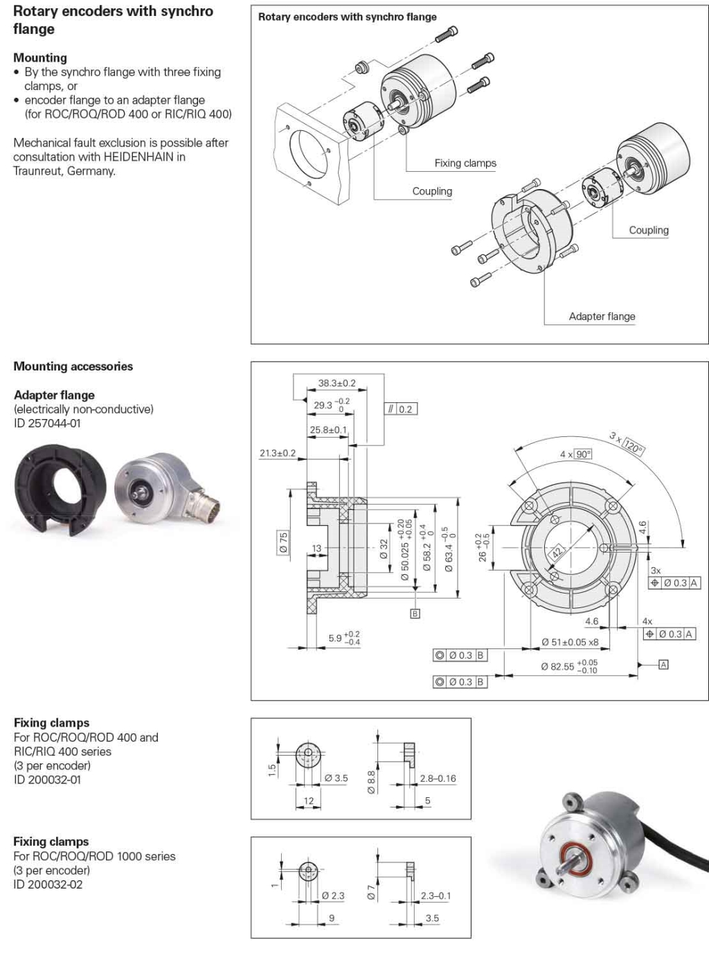
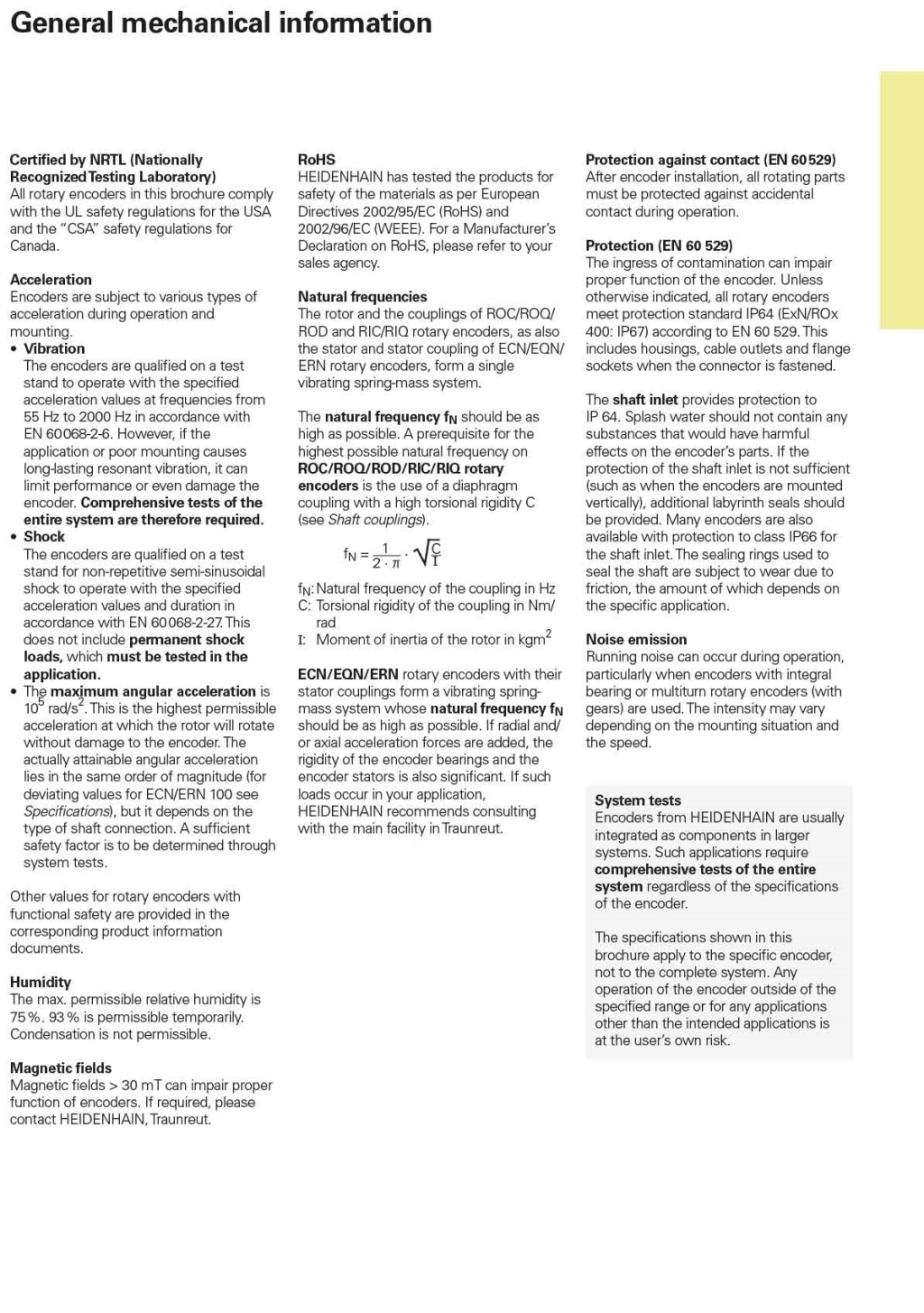
■ Bearing life (h) The bearing life is inversely proportional to the input shaft load. The axial load is the axial load. Both loads are the allowed dynamic loads when the shaft is rotating
■ Axial series (mm) refers to the amount of forward and backward movement of the motor shaft, etc., from the state after installation coding.
■ Radial runout (mm) refers to the amount of deviation of the motor (2 times the amount of eccentricity)
■ End face runout (mm) Fix the shaft so that the end face of the flange surface such as the motor will swing when the flange surface rotates.
■ TIR The full width (degrees) reading indicated when using a dial indicator such as a dial indicator.
■ Starting torque (N.m) Rotates the encoder shaft that is at rest by the necessary torque. Under normal circumstances, the torque in operation is smaller than the starting torque.
■ Allowable angular acceleration (rad / s2) The angular acceleration is the amount of increase in angle (rad) per unit time
■ Allowable shaft load (N) indicates the maximum load that can be added to the shaft, with both radial and axial load. Radial load for the shaft, is the vertical direction, the force and eccentric declination and other related; axial load on the axis, the horizontal direction, the force and the push-pull shaft force. The size of these two forces affects the mechanical life of the shaft
■ Moment of inertia of the shaft (kg.m2) This value indicates the inertia of the rotary shaft and the resistance to changes in rotational speed
■ Speed (rpm) This speed indicates the mechanical load limit of the encoder. If this limit is exceeded, the bearing life will be negatively affected and in addition the signal may be interrupted.
■ Gray Gray codes are advanced data and are safe because they are unit distances and cyclic codes. Only one change per step. Data processing, Gray code to be converted into binary code.
■ Current Consumption (mA) Supplied to Encoder Standard The maximum encoder operating current measured at the mains voltage
■ Allowing the injection current (mA) Voltage output, open-collector output circuit allows the current flowing into the encoder?
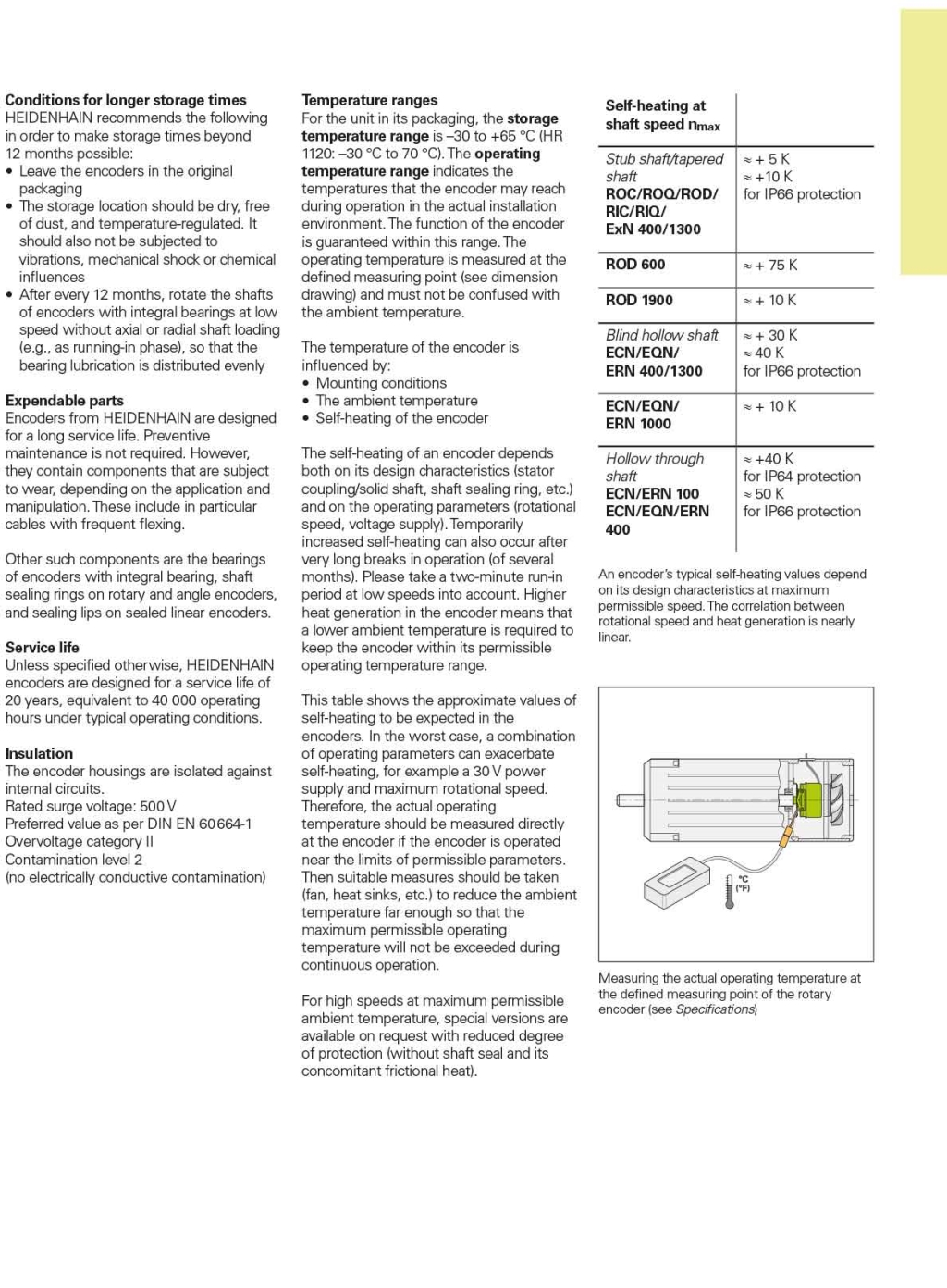
■ Operating temperature (℃) Ambient temperature that meets the parameter, which indicates the external temperature and the temperature of the mounting section (flange shaft)
■ Storage temperature (℃) Do not cause deterioration of rotary encoder function Ambient temperature (no power)
■ Impact resistance (m / s2) Type Evaluation test, the right side of the impact test, and start passing, that acceleration. Conditions: Shock Wave ??? Sine half-wave Impact direction XYZ direction Impact times Each direction 2 times, (6 times)
■ Vibration Resistance (m / s2) Type Evaluation Test, the right side of the impact test, and start passing, said the acceleration. Conditions:? Vibration 10Hz-200Hz Scan period 10 minutes Vibration direction XYZ direction Vibration time 2 hours in all directions (total 6 hours)
■ Accuracy (rad) The difference between the swing angle and the theoretical swing angle obtained by adding the number of output pulses
■ Cycle Error (rad) The difference between the number of output pulses and the number of theoretical pulses
■ Adjacent Period Error (rad) The difference between adjacent cycles
■ Output code system includes: Natural binary code Natural binary code Gray code Cyclic binary code Yu Gray code For a rotation of the sub-degree is not a power of 2 cyclic binary code. BCD code ??? 2 - Decimal symbols: The lines of the decimal symbol are individually converted to symbols of binary symbols Positive logic symbol 1 is high 0 is low
■ Negative logic 0 is high - 1 is low
■ Transmission Distance Pulse signal transmission distance related to the following factors, the frequency, the output circuit, the input circuit, the transmission line, the transmission frequency Q. Encoder installation precautions
-
Absolute Encoder1) What is the difference between single-phase rotation and multiple rotation? Single-phase rotation: the encoder rotary axis range of a split, rotary 1 week after the initial data can be displayed, so a total of a few times can not be judged. Multiple rotations are: The number of revolutions of the encoder’s axis is counted, and in the event of a power failure, it also has the function of counting the revolutions of the encoder’s axis.
(2) into the binary output, under what circumstances can read data? Only limited to the absolute encoder, read data in two ways: In the output signal is read when the level of conversion is static and read the data in a certain period of time is the law. From the detection accuracy point of view, the use of static method is more accurate, but if the use of dynamic methods can shorten the read cycle and can reach the same precision with the static method.
(3) multiple rotary absolute encoder, the power failure, the rotation of the data can be added? When the maximum number of revolutions described in the manual is less than the maximum number of revolutions, the data at power failure can be added.
(4) How to reset the data of absolute encoder? Single-phase rotary is unable to reset the data. But can accept annunciator, any data can be set to 0, the effect is the same as reset. Rotary number of times the number of rotary data, you can enter the reset signal to reset. Two-way communication model (our company’s ASE, ASF), etc., but also set the data in advance.
(5) What is the cause of an error when the encoder reads data? Wrong wiring possible. If it is on a regular basis, it may be affected by the noise, it is recommended to read multiple times.
-
Precautions For Correct Use of Rotary EncodersFirst, the mechanical aspects
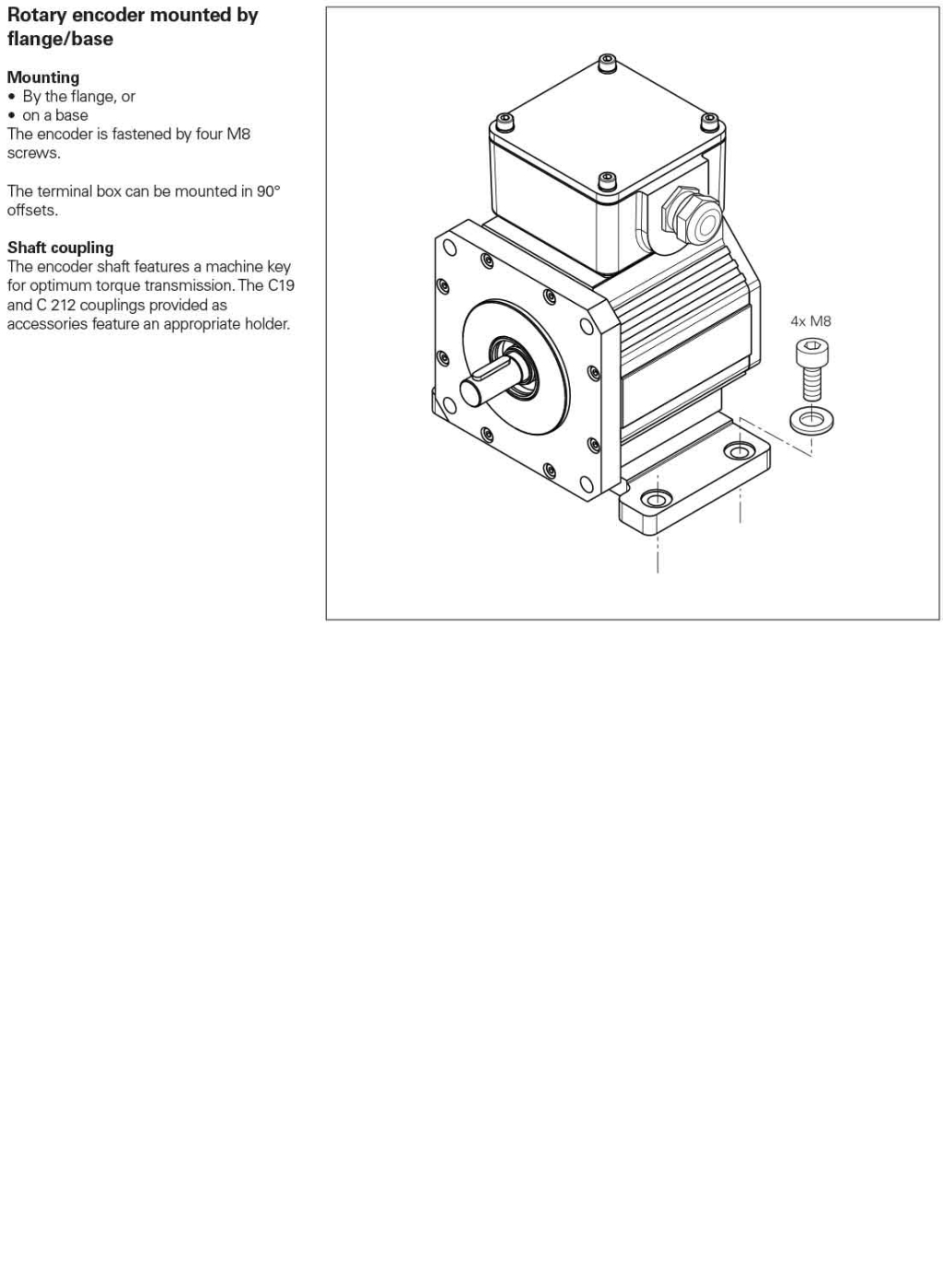
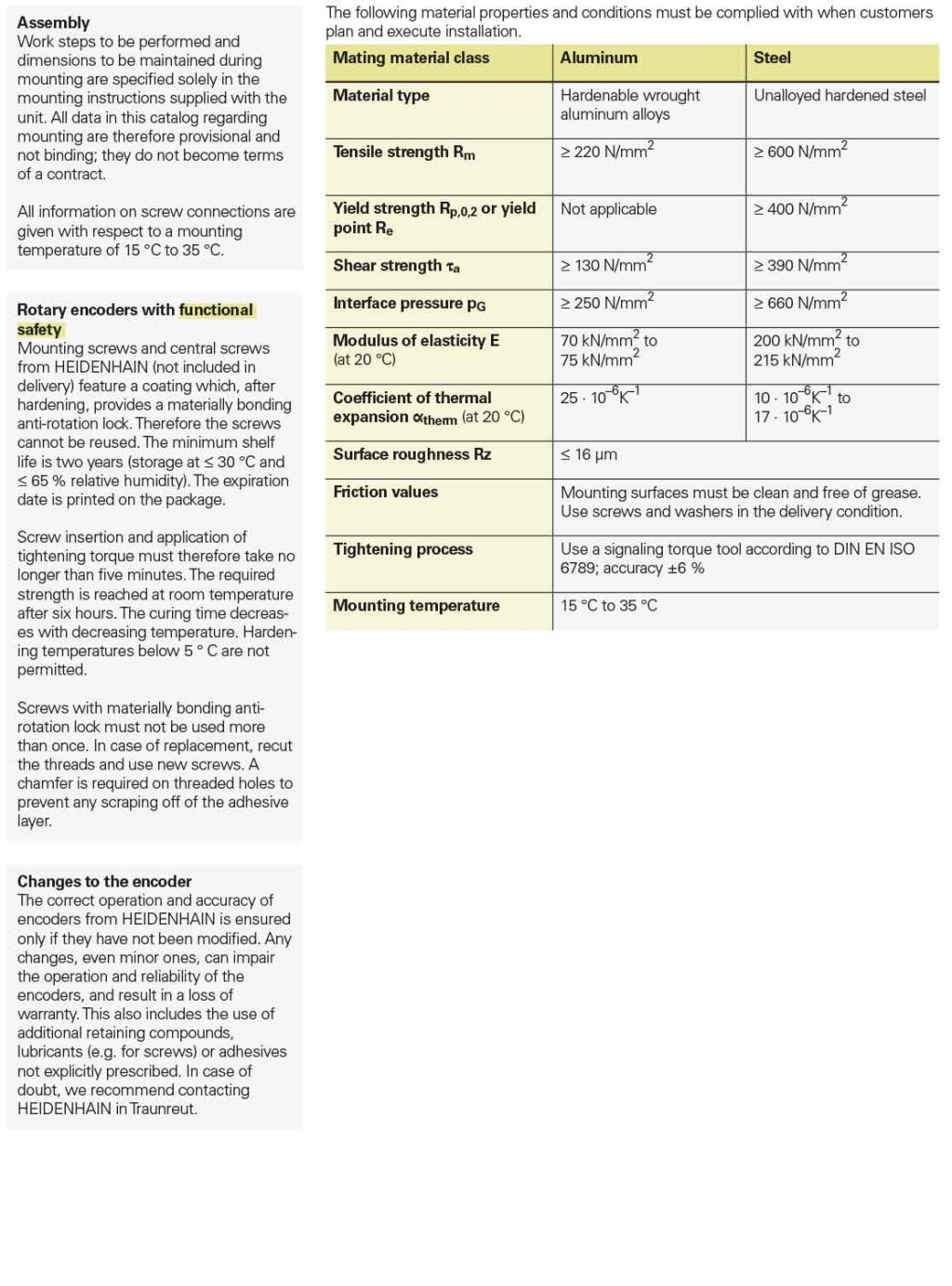
(1) Solid shaft: 1.1 Encoder shaft and the user-side output shaft should be flexible between the soft connection to avoid the user’s shaft string, beating, resulting the damage of the encoder shaft and encoder. 1.2 installation should pay attention to the allowable shaft load, must not exceed the limit load. 1.3 Should ensure that the encoder shaft and the user output shaft of different axis <0.20mm, with the axis of the declination <1.5 °. 1.4 Hit and collide are forbidden for installation, in order to avoid the damage of encoder shaft and encoder.
(2) hollow shaft categories: 2.1 To avoid contact with the encoder steel, plate springs should be used. 2.2 Please pay attention to the installation of the shaft load, the encoder should be gently pushed into the sleeve shaft, using cone to hit is strictly prohibited, so as not to damage the shaft and encoder. 2.3 The installation shaft must meet the following requirements: Axial series <0.5mm Radial runout <0.1mm End runout <0.1mm. 2.4 long-term use, please check the plate spring on the encoder is loose; fixed encoder screw is loose.
Second, the electrical aspects
(1) Please do not enclose the output line of encoder and power line or the like in the same pipe, and should not be used in the vicinity of distribution panel.
(2) Shielded cable should be used when wiring.
(3) should be carefully checked before starting, the wiring is correct.
(4) long-distance transmission, signal attenuation factors should be considered, the choice of low output impedance, anti-interference ability of the output.
(5) Be careful not to exceed the limit speed of the encoder. If it exceeds the limit speed, the electrical signal may be lost.
Third, the environment
(1) Because the encoder is a precision instrument, it should be noted that there is no vibration source around.
(2) Encoders that are not leak-proof structures Do not splash water, oil, etc., and attach a protective cover if necessary.
(3) Please pay attention to whether the ambient temperature and humidity are within the requirements of the instrument.
-
Incremental Rotary Encoder(1) Is there any way to check if the incremental encoder pulse leaks? The pulse from the origin position to the next origin position is counted to check whether the pulse leaks. In addition to the encoder rotation speed, but also the magnitude of the pulse measured to determine whether the pulse leakage.
(2) Incremental Encoder counting error causes what? There are several possibilities for counting errors. First, there is a runaway between the encoder shaft and the drive, resulting in a count error. At this time there will be on a regular basis a large number of count errors. Second, counting errors can occur due to noise and other effects. This is also on a regular basis, but only a small amount of technical errors can be considered as being affected by noises.
(3) Only encoder can determine the location of the origin? Z signal under what circumstances the output If the Incremental encoder has a Z signal, the origin position can be determined In order to match the encoder’s counting position with the origin, follow the A, B, and Z signal theory when determining the origin position. Example: Absolute Encoder can set the origin anywhere
-
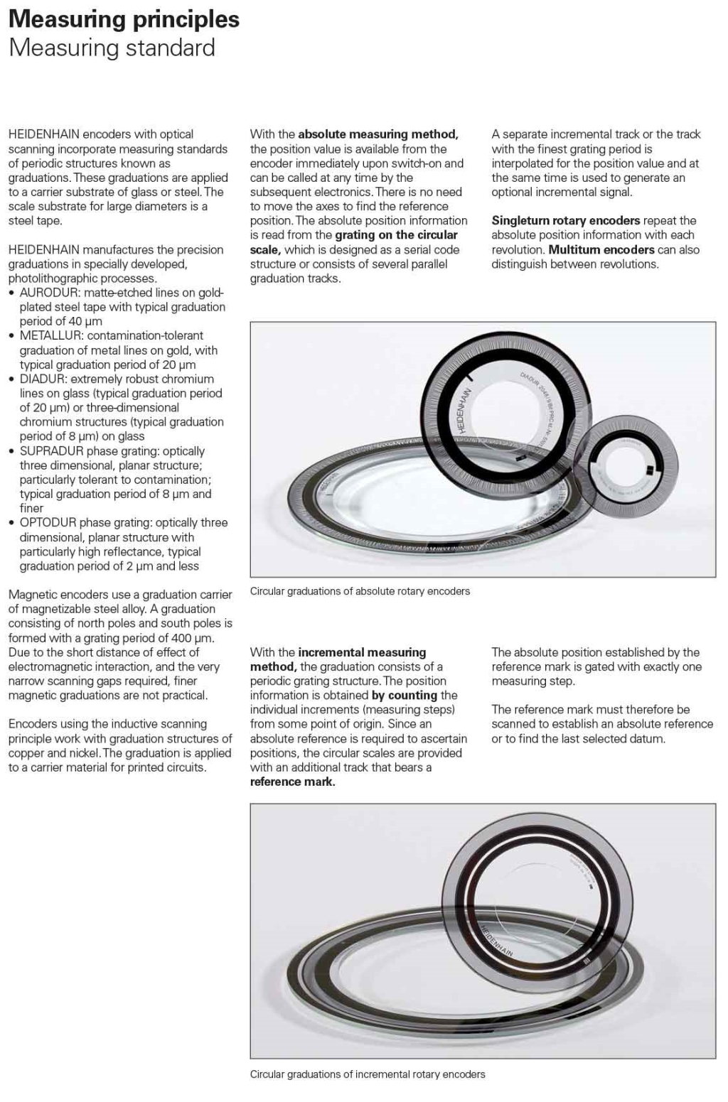
Standard measuring step of Rotary Encoders
-
surroundings of encoder
-
suggestion for signal wire of encoder
-
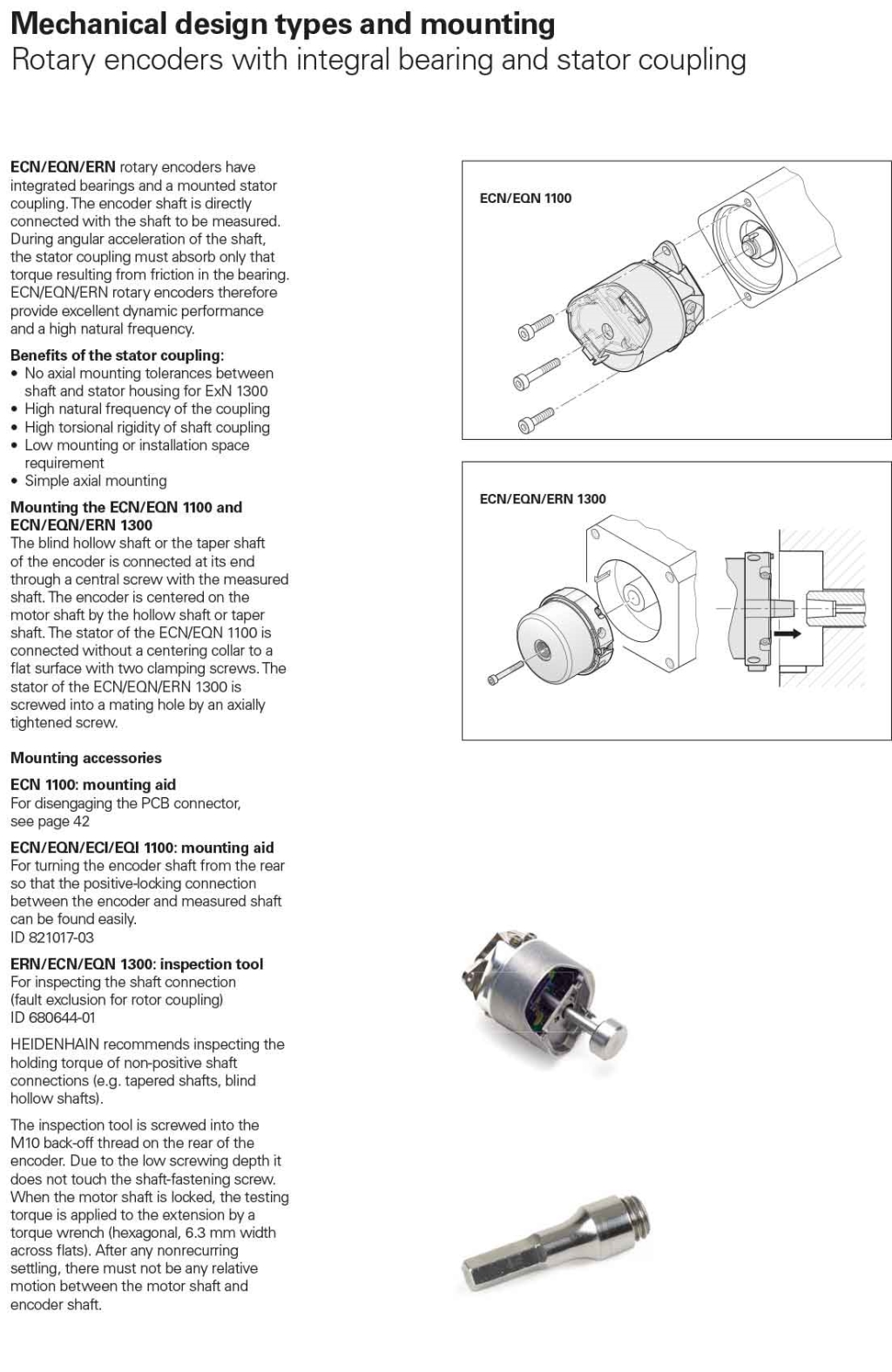
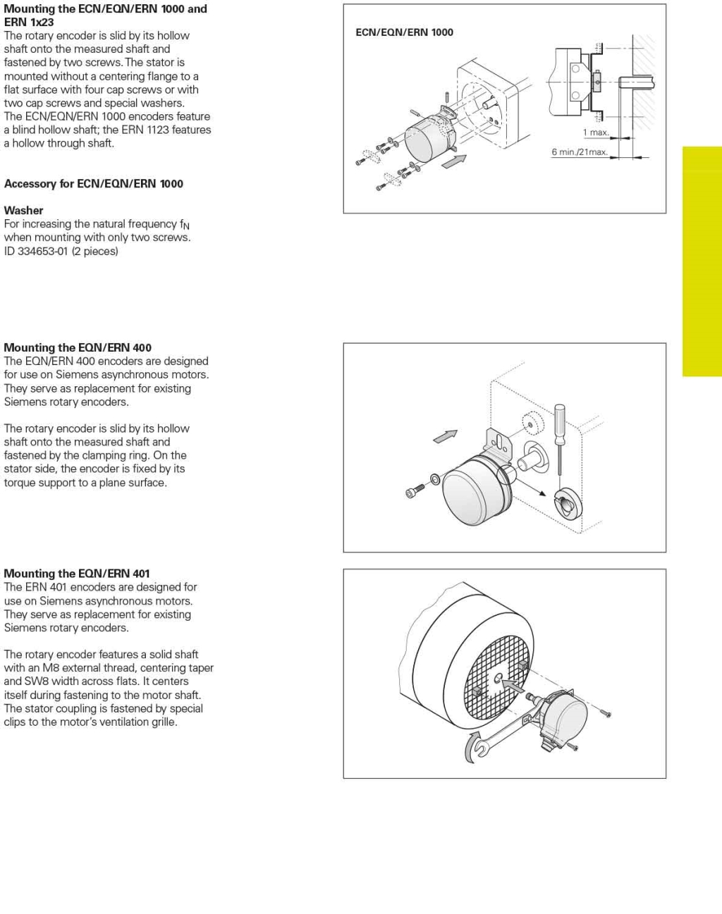
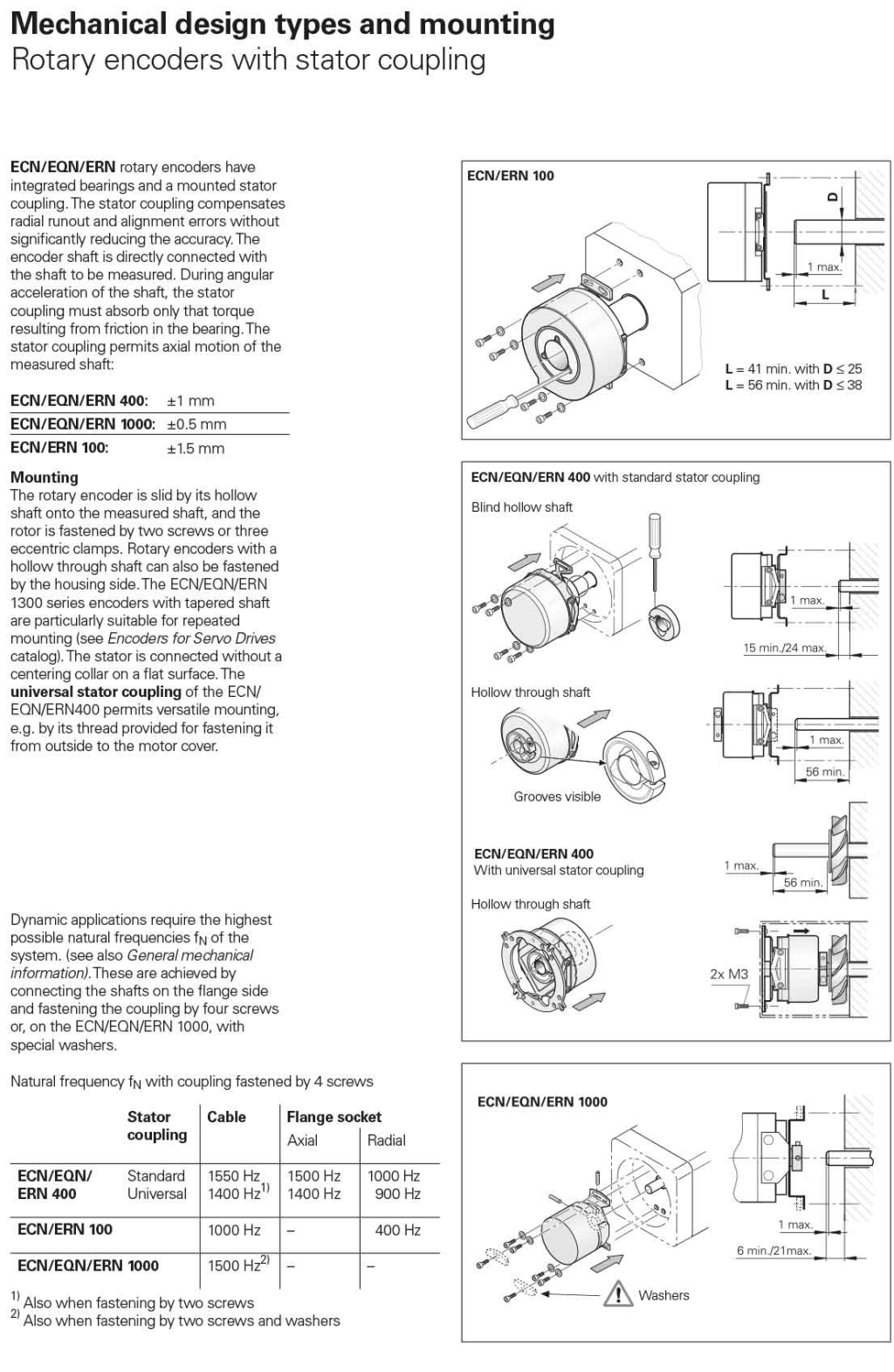
Mechanical design types and mounting of Rotary Encoders
-
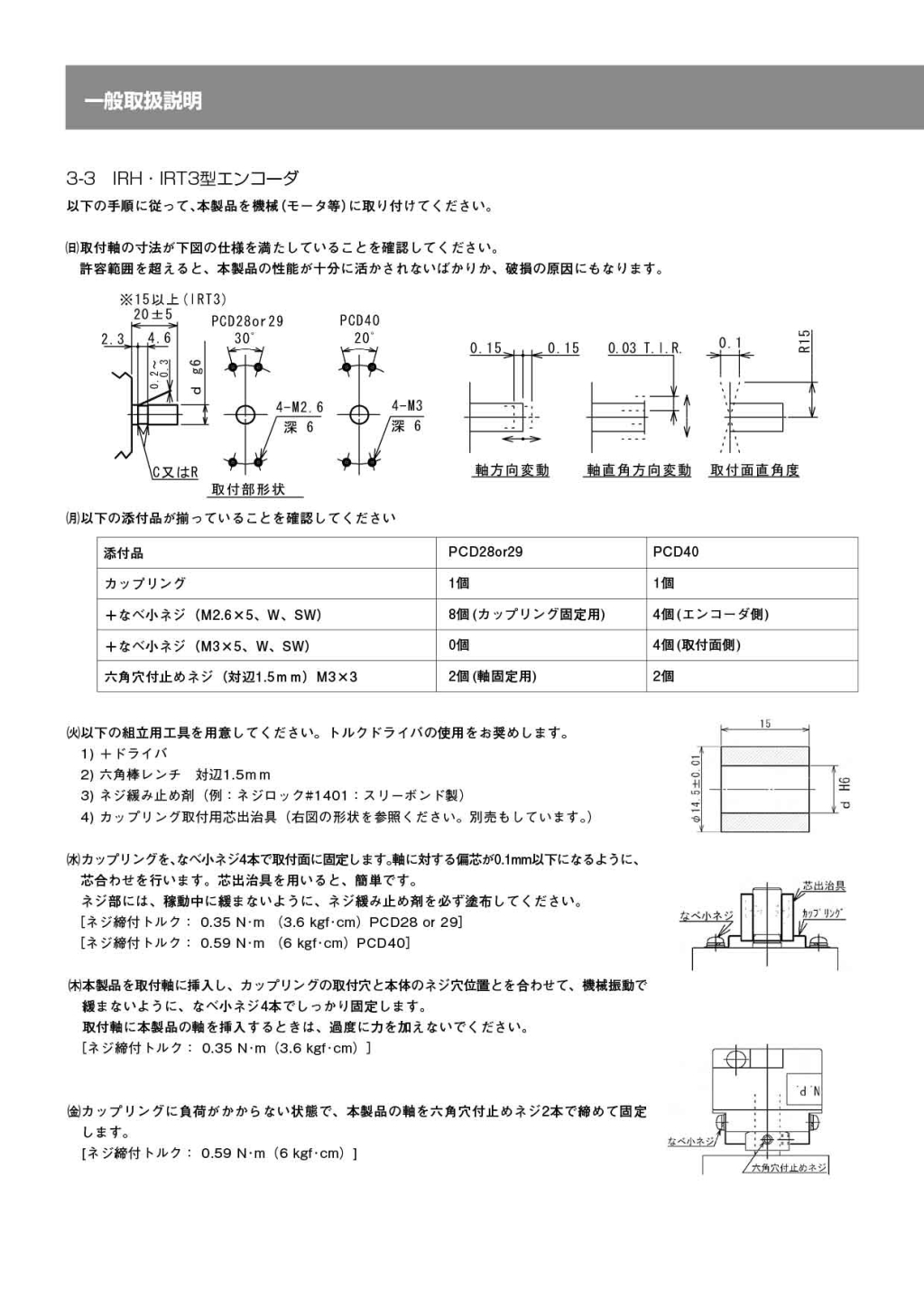
IRH / IRT3 Encoder mounting
-
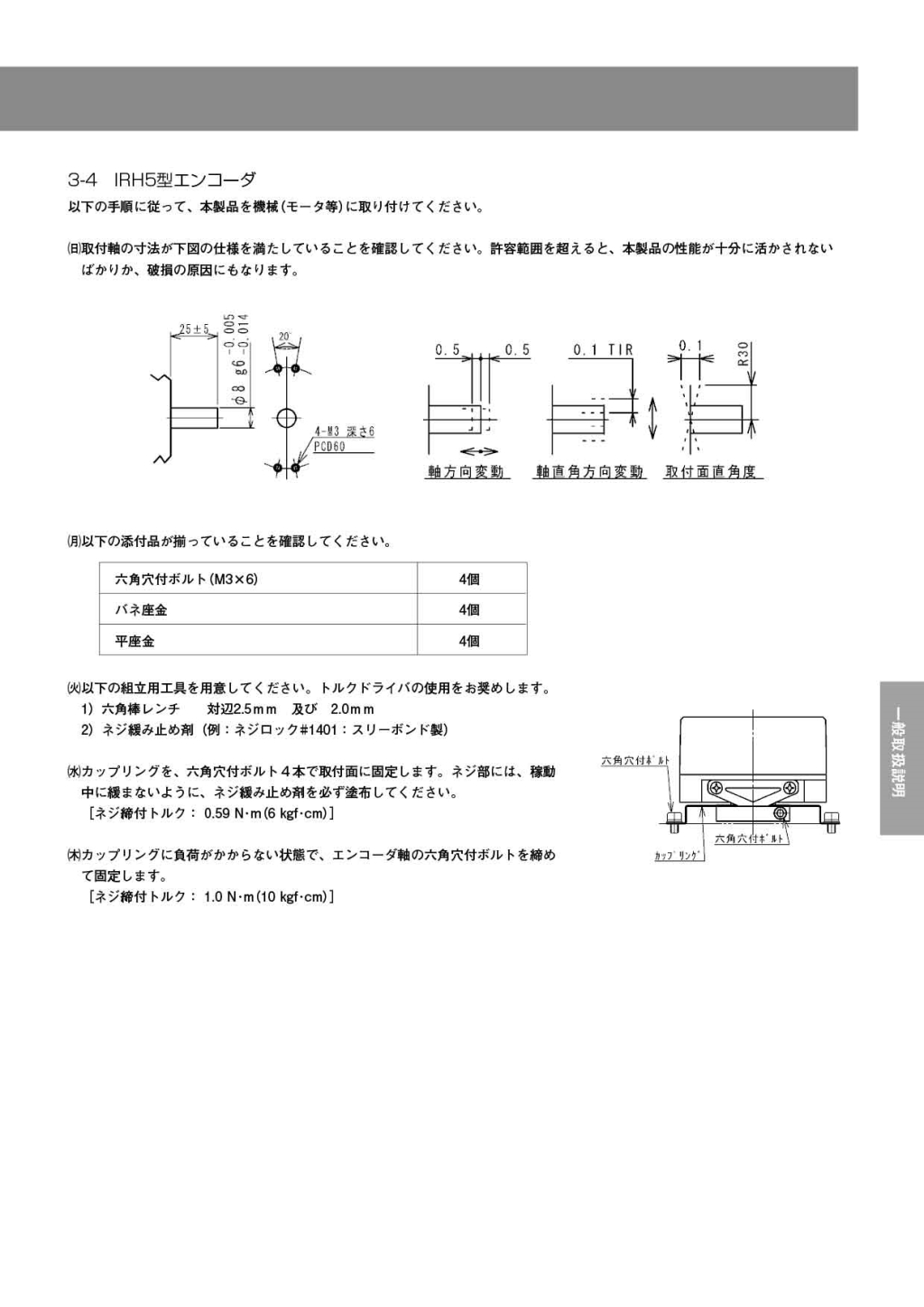
IRH5 Encoder mounting
-
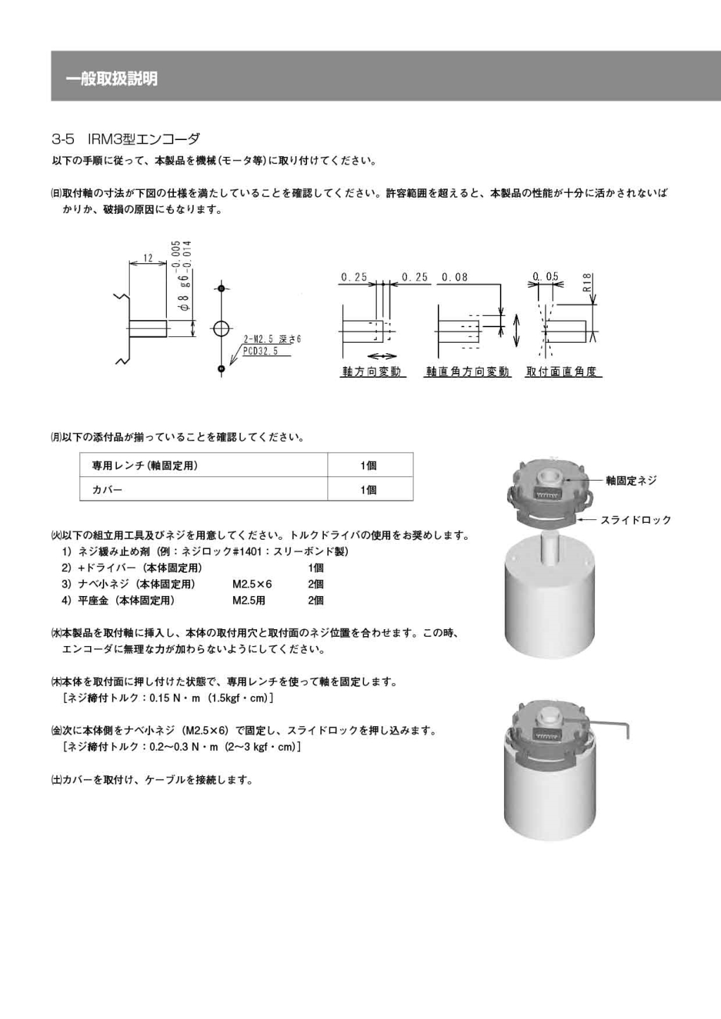
IRM3 Encoder mounting
-
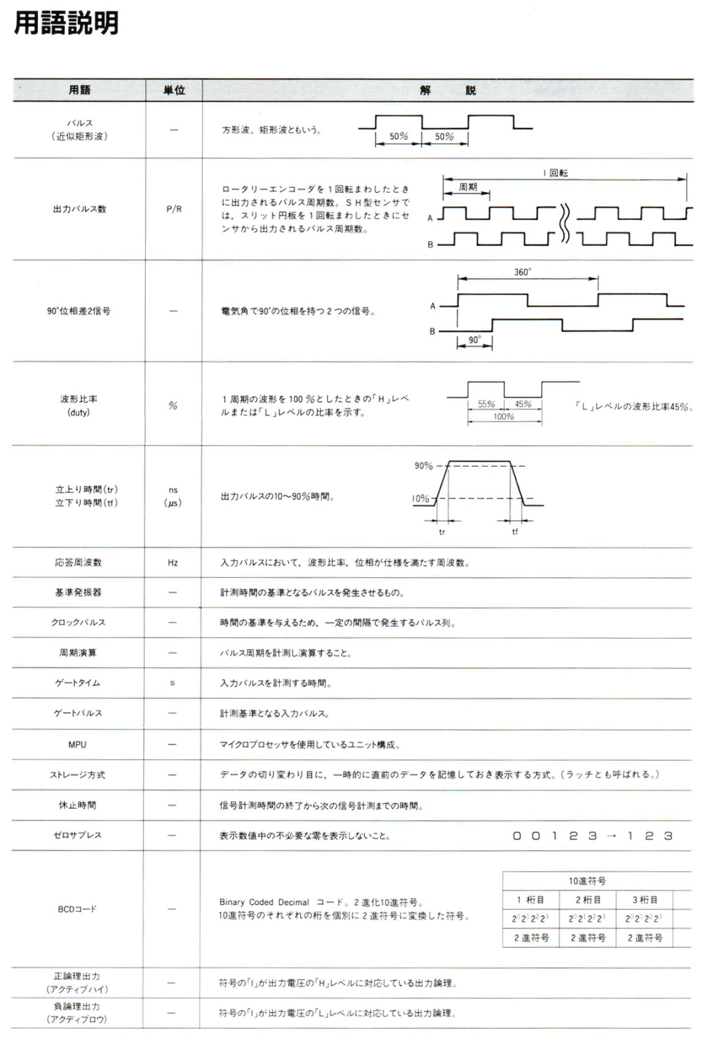
Encoder word Part.1
-
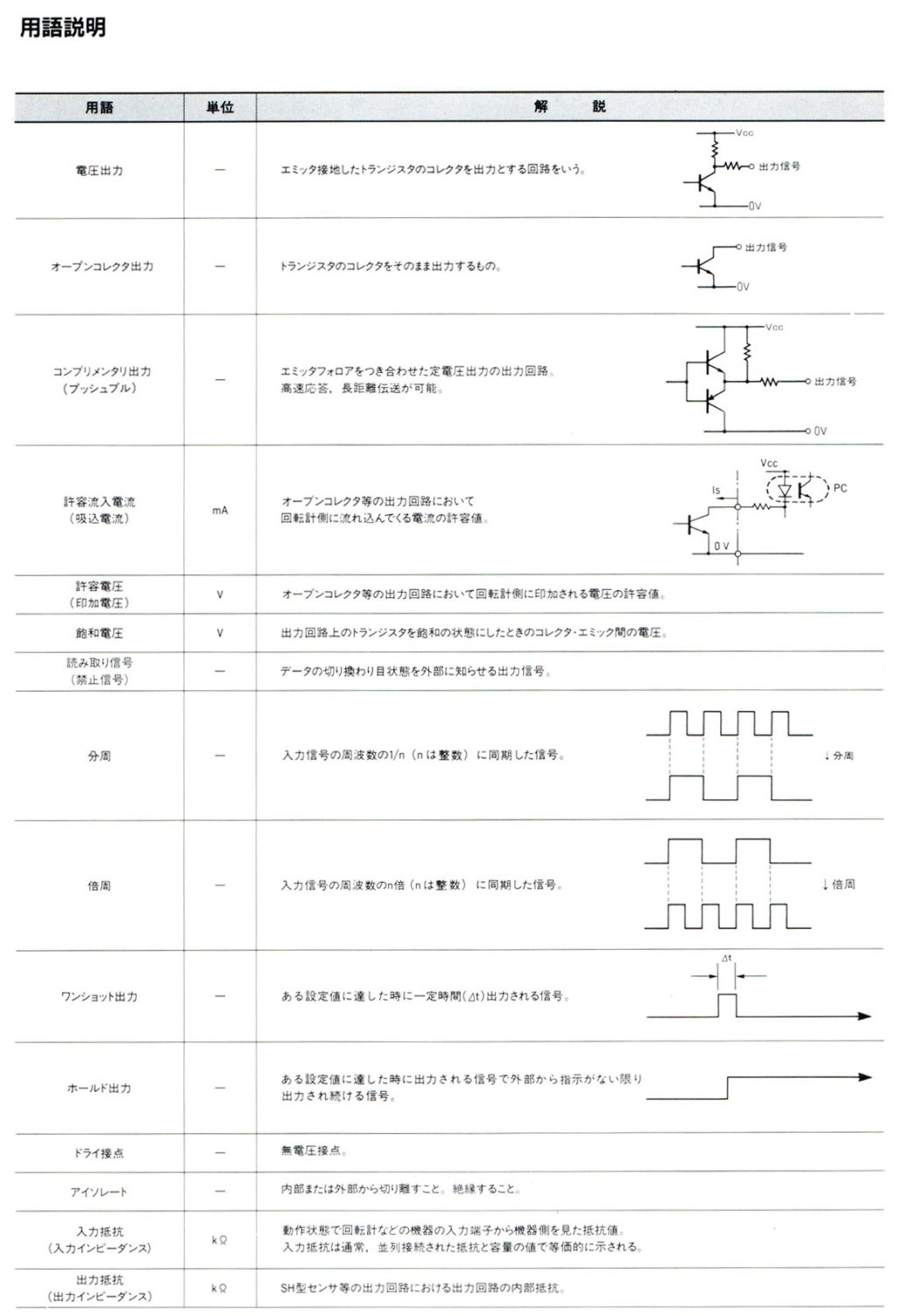
Encoder word Part.2
-
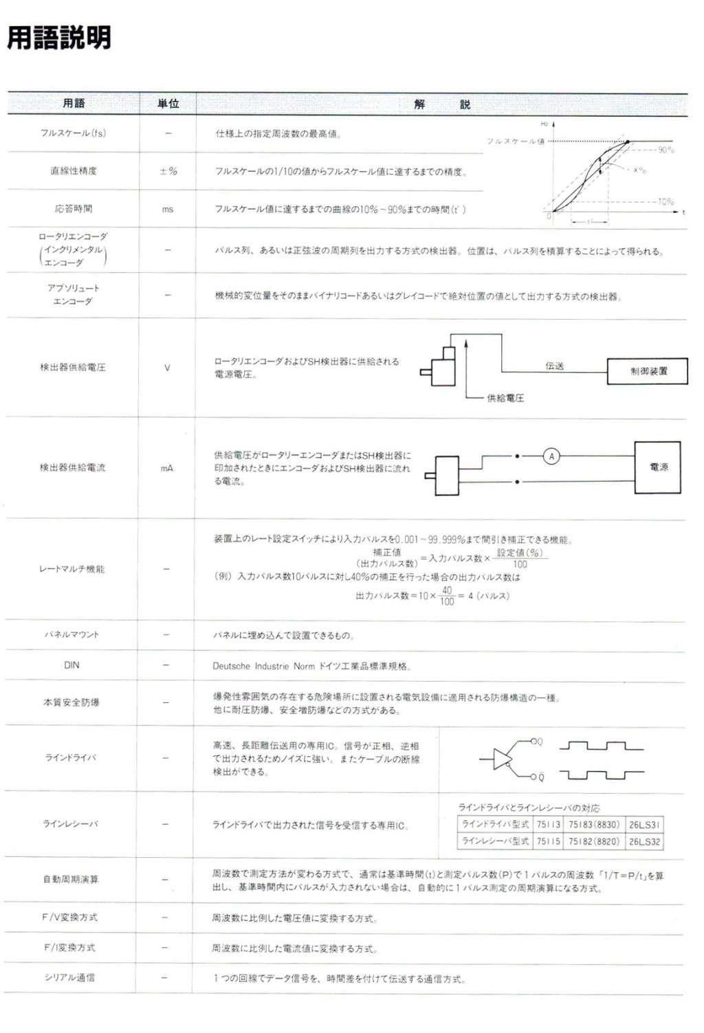
Encoder word Part.3
-
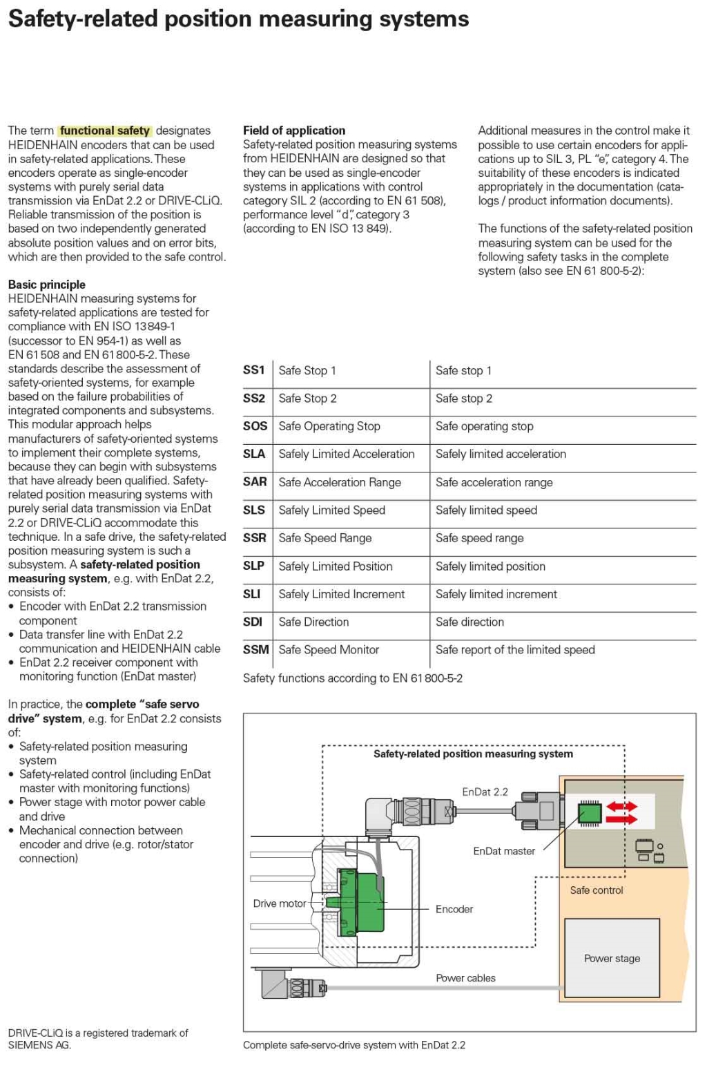
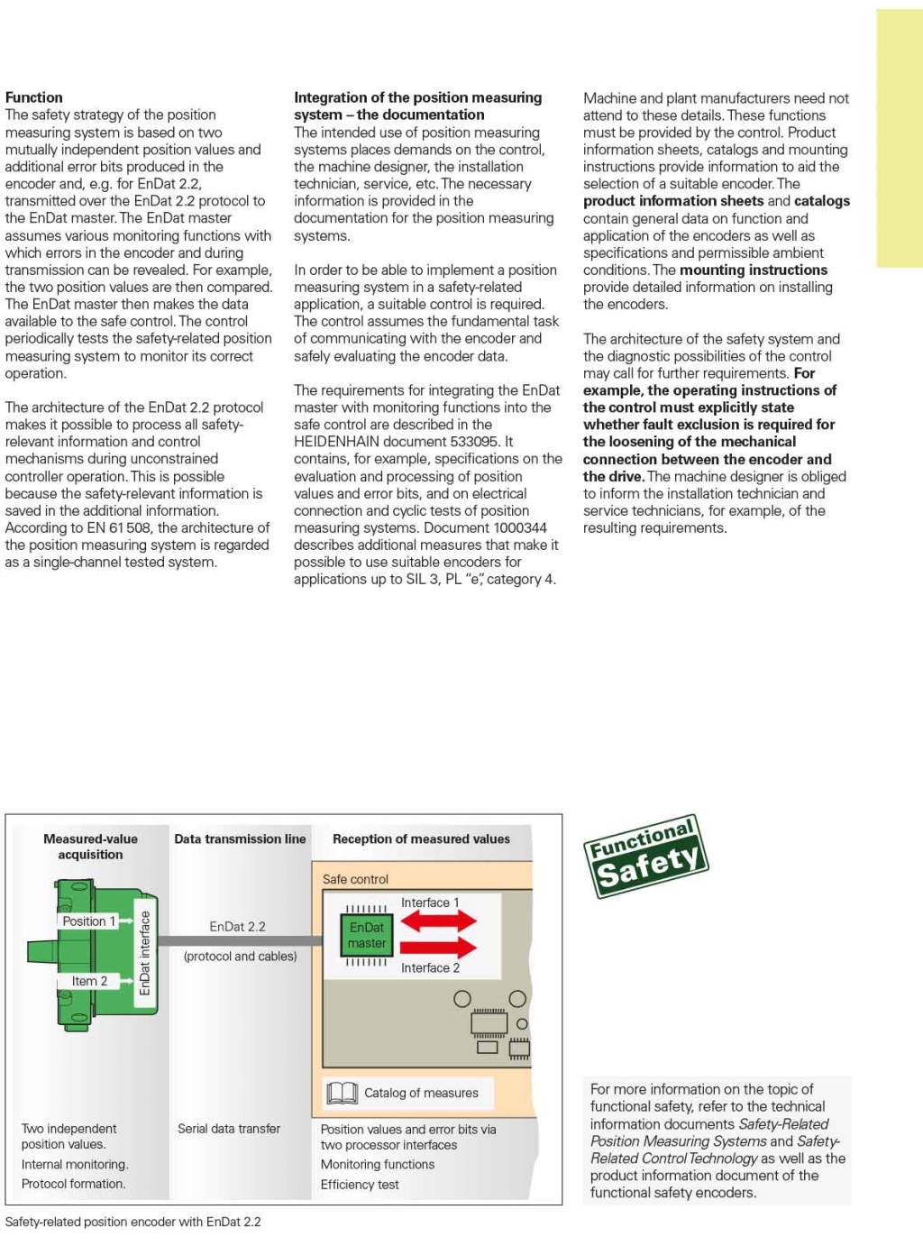
Safety position measuring systems
-
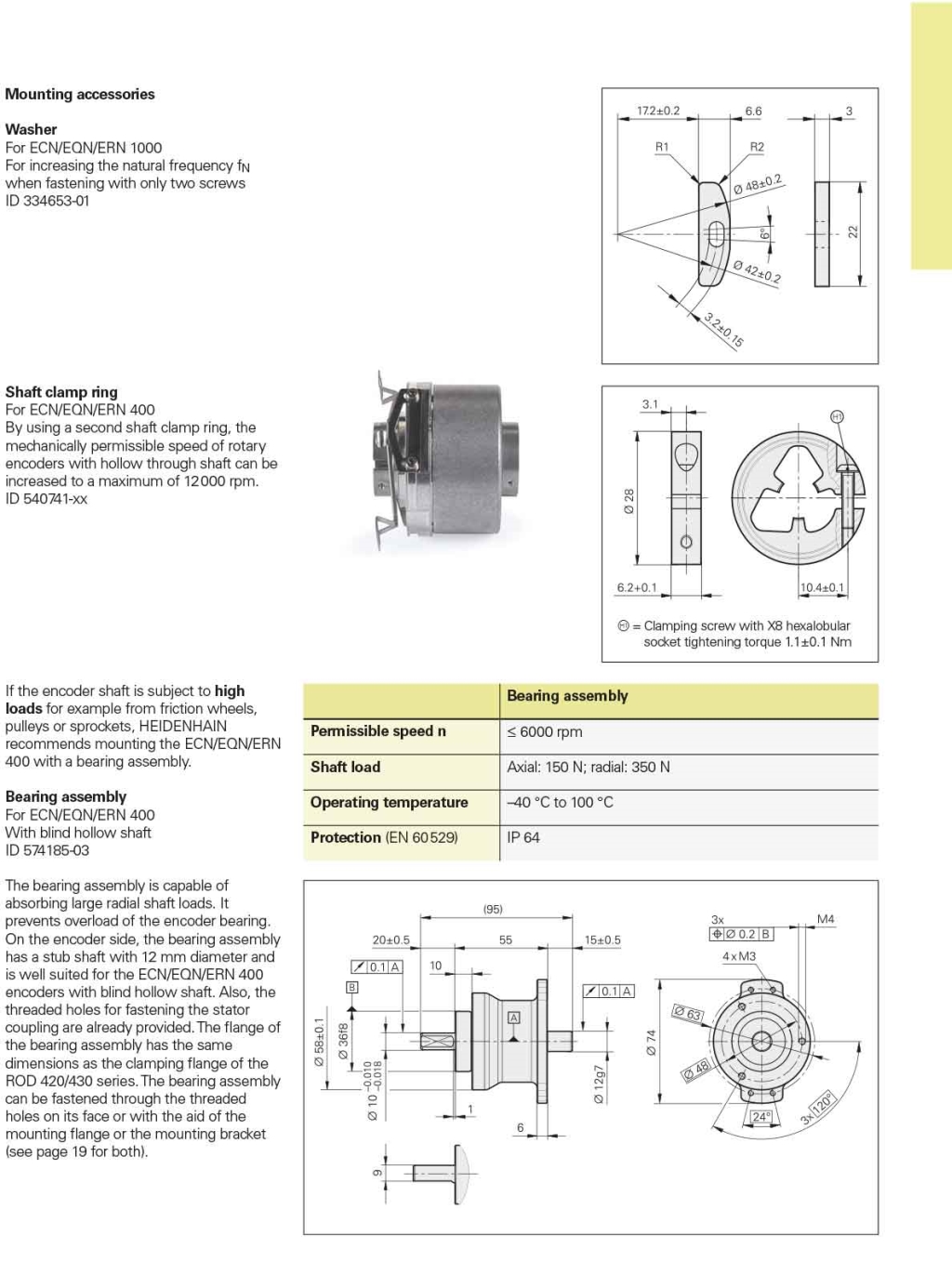
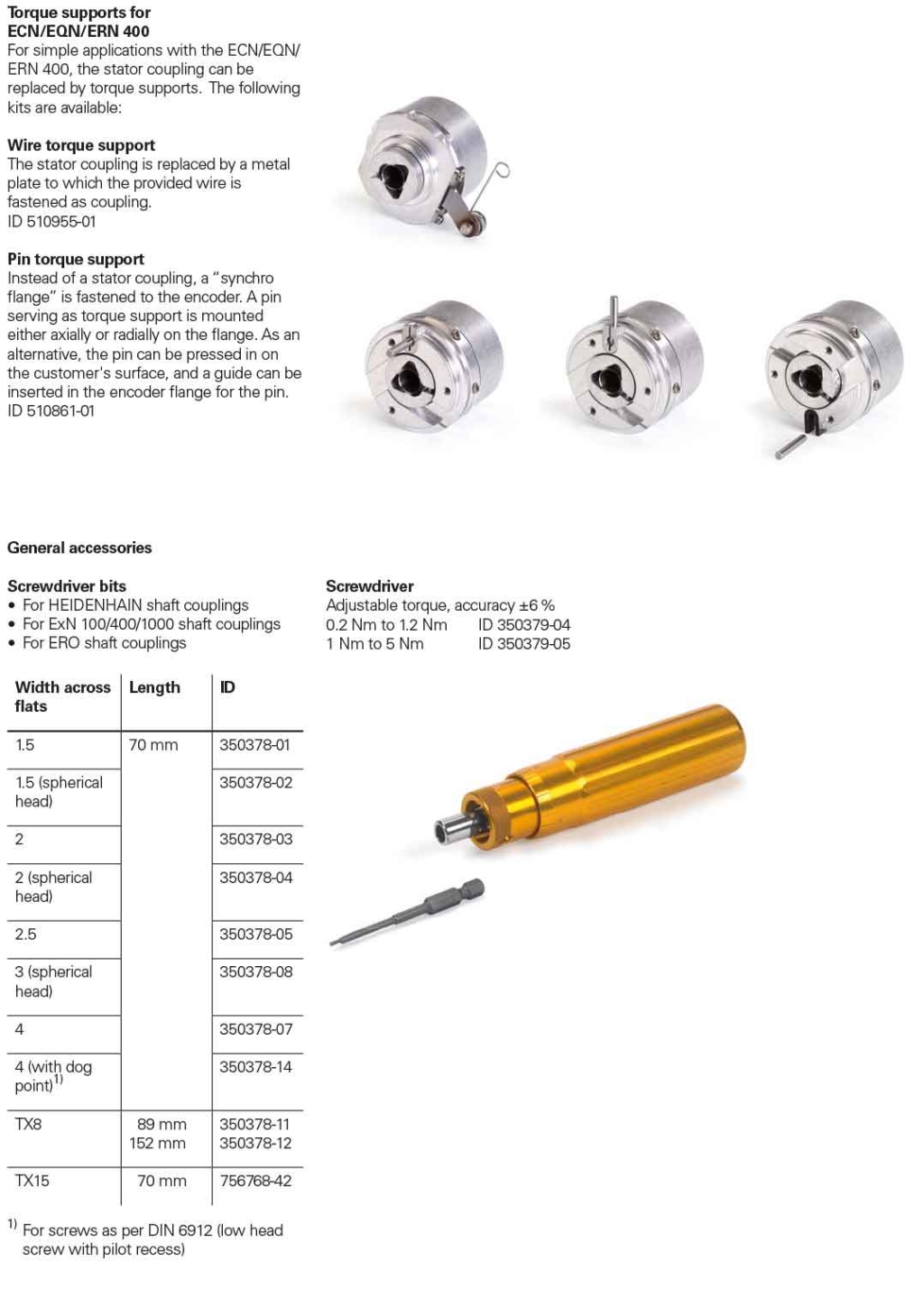
Encoder type & Mounting
-
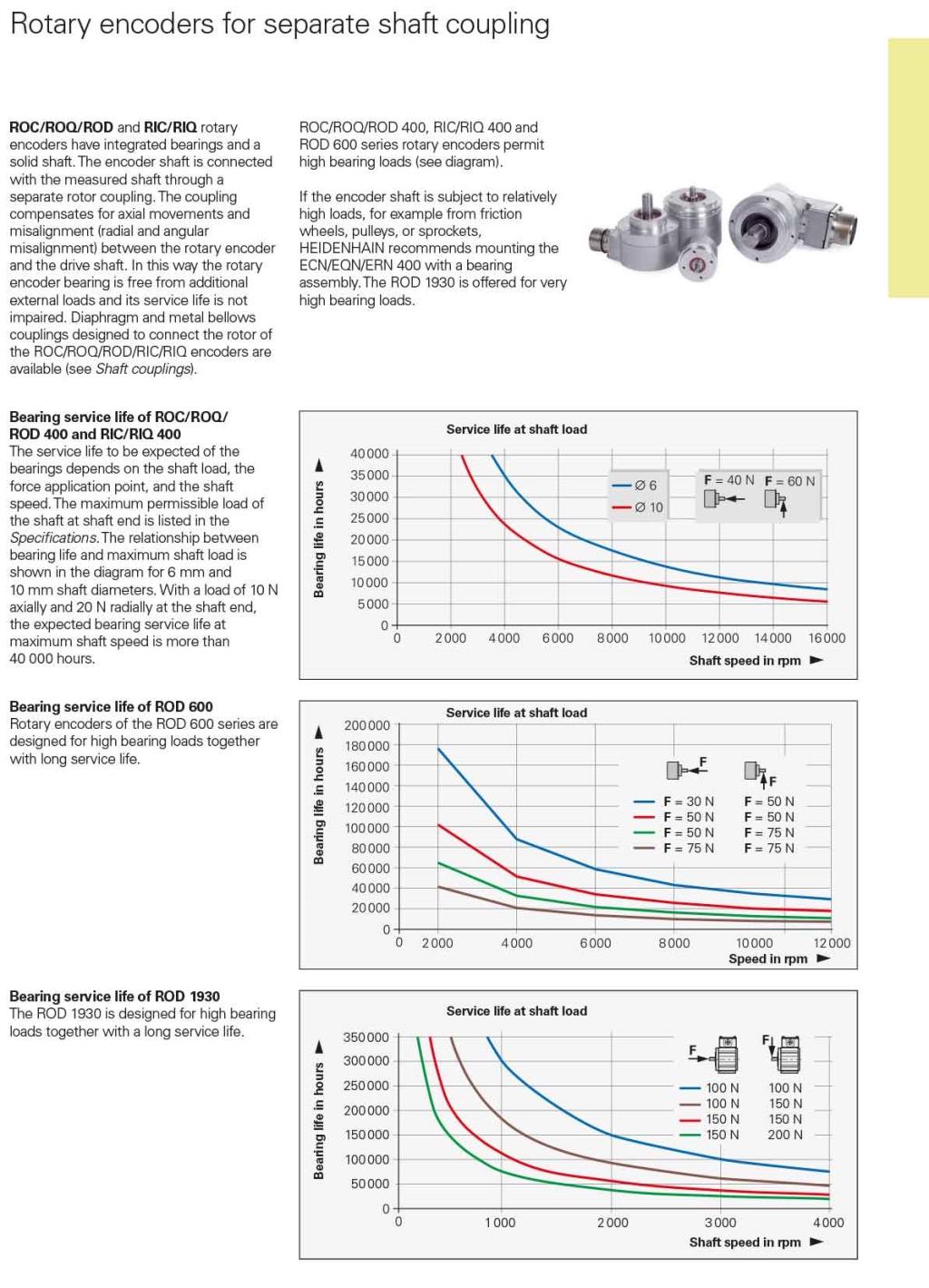
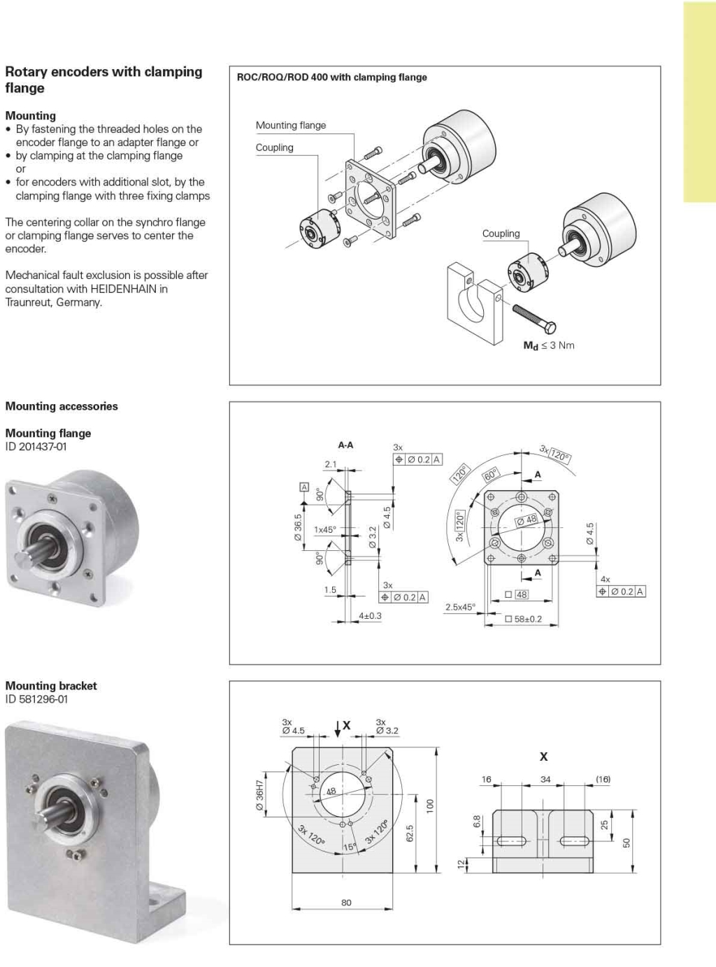
Connection with Encoder & Coupling
-
Mechanical information of Encoder
-
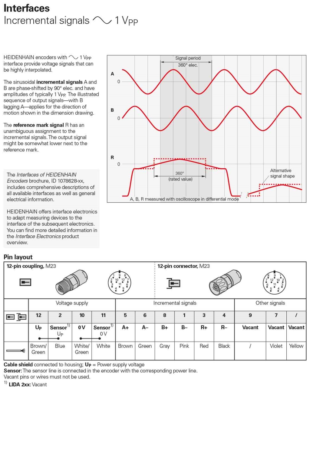
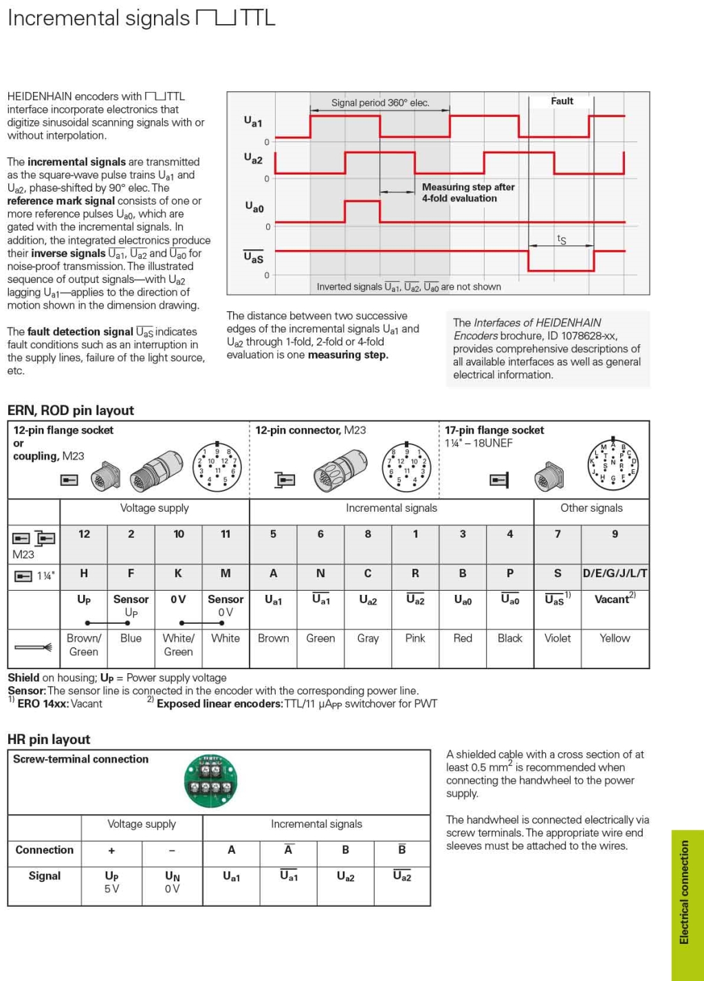
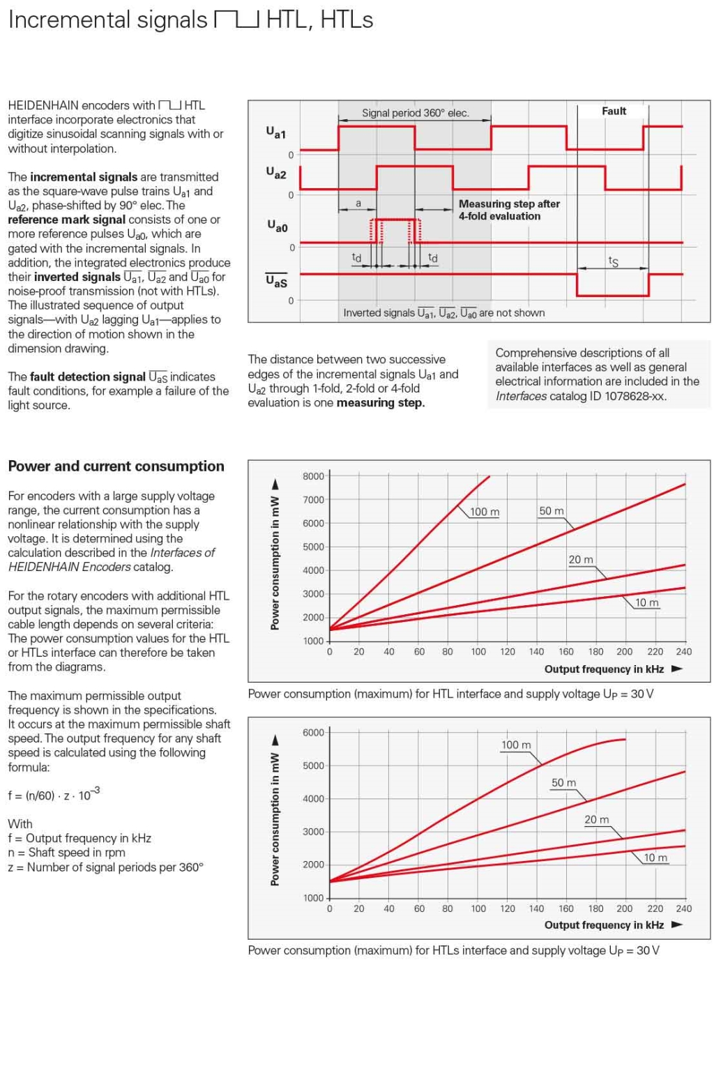
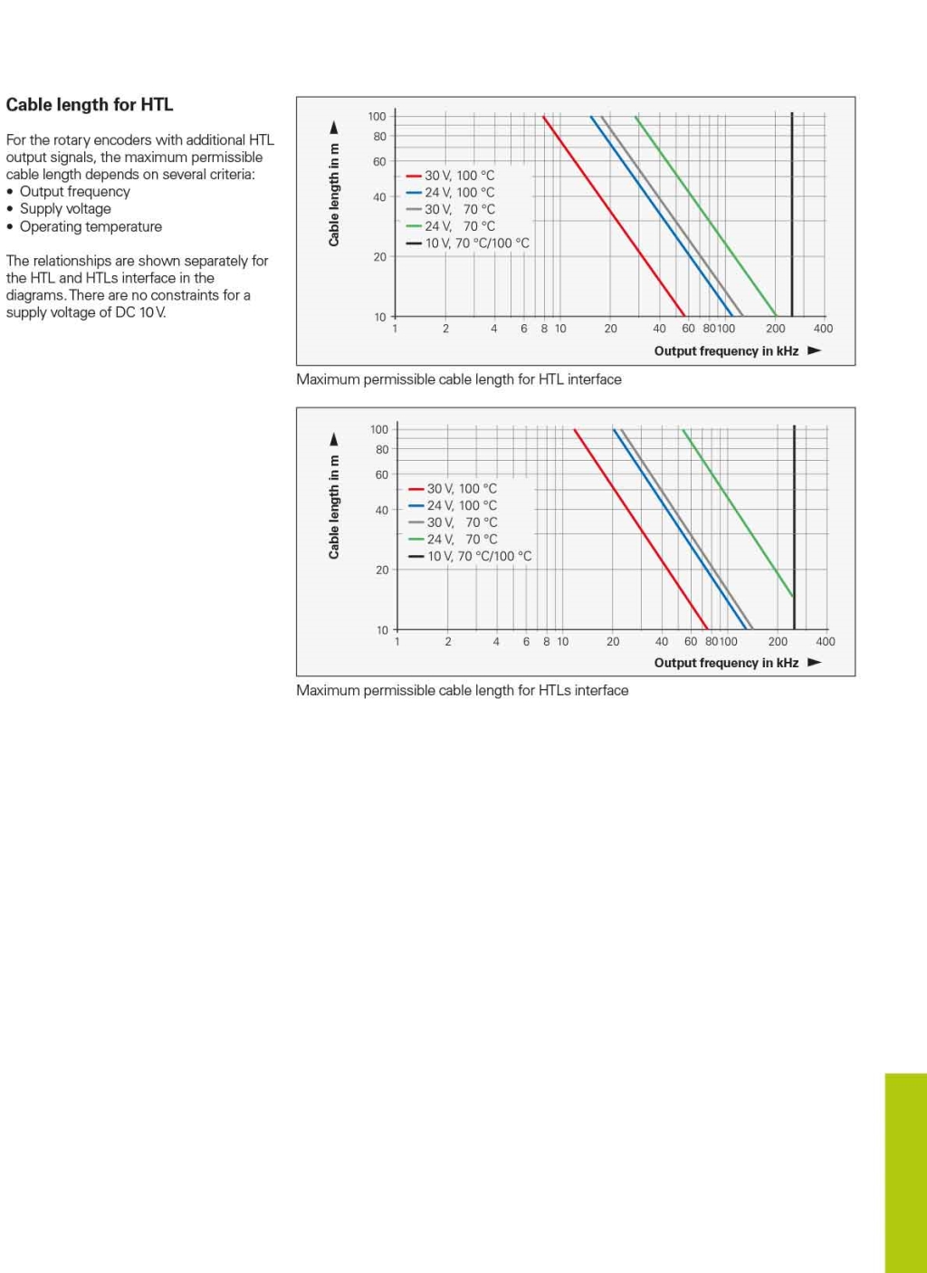
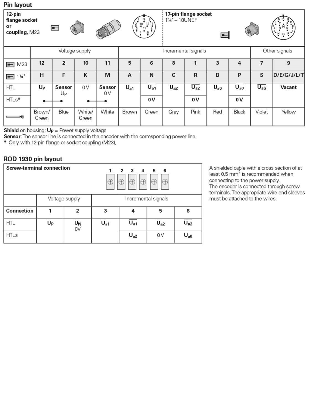
Incremental signals ~ 1 VPP
-
Safety applition of all kinds of encoderSafety applition of all kinds of encoder
Before use (installation, wiring, operation), be sure to carefully read the "safe use" and other attachment files,
Please familiarize yourself with all the equipment knowledge, safety information and precautions before using it.
(Storage enviromernt)
‧Avoid using counter under enviroments as bellow if it’s possible:
‧Dusty
‧Wet
‧ corrosive gases
‧Electrostatic
‧High vibration & impact
‧Near Water / steam / oil
‧Direct sunlight
‧ If the power drops during operation due to lightning strikes or the like, check for any differences before restarting.
‧Keep the temperature within the specified range: It is recommended to use it after it is stored at -10 ° C. In addition, place it at room temperature for more than 3 hours and ensure that the instrument does not dew and drip. Confirm before energizing.
(installation)
‧ There is no special restriction on the installation direction, but try to fix it in the horizontal direction. In addition, when installing many instruments side by side, pay attention to the distance between the left and right sides.
(Connecting & wiring)
‧Connect the power cord to the terminal number on the main label according to the terminal connection diagram or instruction manual. If it is connected to other terminals, it will damage the firearm or catch fire. Please note there is danger.
‧ It is recommended that the wire cross-sectional area of the power cord is 1.25m㎡ or more (AWGI 6 or less).
‧ Connect the detector cable to the terminal number on the main nameplate according to the terminal connection diagram or unwanted instructions. If you connect to other terminals, you can damage the device, be careful because of the risk.
‧The ground terminal can be designed so that the grounding resistance of the ground part is less than 100Ω.
‧When used in an environment where surges or noise surround the power supply, use a surge absorbing element or noise filter and place it near the instrument and wire it.
‧Connecting power cables, input / output cables, detector cables in parallel with high-voltage lines and power lines may result in malfunction or disconnection, so separate them by more than 30 cm and route them as short as possible through the other path. In addition, use a shielded cable or metal conduit as the detector cable, separate from the noise source and the strong wires, and keep the wires as short as possible.
‧When the transmission distance is longer, consider the inductance and capacitance of the cable to be used
(operation)
‧Before operation, be sure to make sure that the connection is secure (loose screws or incorrect connection).
‧Please provide the voltage (SOURCE) within the specifications of the motherboard terminal number. Providing voltage in excess of the specifications may damage the instrument.
In addition, voltage fluctuations should be within specifications. If the volatility is large, it may not work properly.
‧Do not use a power supply with a gradually changing voltage (SOURCE). Voltage immediately rise to the rated power (SOURCE) Please use such a power supply.
‧Do not use the output relay directly drives a large motor. We recommend that you use a medium (large) solenoid switch to relay once. In addition, turning on and off the inductive load If this occurs, back EMF may occur and the instrument may be damaged. Therefore, use it as a back-EMF absorbing element, a diode for a DC circuit, a convex wave absorber, or the like.
‧Use the load current that controls the output contact at rated load. If used above the rated value, the contact life is significantly reduced, if it is the transistor circuit will cause damage to the transistor.
‧Do not apply any voltage error to the control input terminals (signal - COM), which may damage the input circuit.
(other)
‧The maximum frequency of the specification input response is the response frequency at a waveform ratio of 1: 1. Therefore, depending on the waveform ratio, it is possible to respond even within the specification response frequency range. As it may be damaged, use a detector with a good waveform ratio whenever possible.
‧Do not operate outside the instruction manual. In particular, do not do this test if you are testing resistance or withstand voltage, as this may damage the instrument.
‧When wiping the dirt on the instrument, do not use solvents that will thin the resin or paint. Recommend to use alcohol when removing dirt. However, be careful not to infiltrate the inside or the inside of the unit.
‧When operating the internal switch such as frequency division setting, be sure to turn off the power beforehand. In addition, care should be taken to prevent contamination of foreign objects (especially metallic objects).
‧If secondary damage may occur due to a malfunction of this product, please provide another protection device and take countermeasures.
-
Safety applition of CounterSafety applition of Counter
Please kindly be sure read the safety installation & other documents before installing / wiring / operation
(Storage enviromernt )
‧Avoid using counter under enviroments as bellow if it’s possible:
‧Dusty
‧Wet
‧ corrosive gases
‧Electrostatic
‧High vibration & impact
‧Near Water / steam / oil
‧Direct sunlight
‧Store in the specified temperature range.
( installation)
‧Horizontal installing should be as safe as possible. In addition, use metal sheet with thickness of 2 ? or more.
(Connecting & Wiring)
‧According to the terminal connection diagram or instruction manual,Connect the power cord to the terminal number on the main label。 Ifconnected to another terminal,Damage to equipment or fire Please be aware of danger。
‧recommended that the power cord for more than 1.25m ㎡ (AWGI 6 or less)。
‧recommend using twisted pair shielded cable with a cross-sectional area of 0.5 m㎡ or more (AWG 20 or less) to connect the detector cable.。
‧The encoder thick line is the ground line,The thick line of the encoder is the grounding line, which needs to be connected to the grounding terminal. Ground part of the resistance, to be less than 100Ω.
‧When used in an environment with power surges or noise,Use a surge absorbing element or noise filter to place it near the instrument and wire it
‧ Connecting power cords, input / output cables, and detector cables in parallel with high-voltage lines and power cords may result in malfunction or malfunction and may therefore be separated by a distance of 30 cm or more with the piping as short as possible.
Meanwhile, use shielded cable or metal conduit as the detector cable, away from the interference source, high-voltage power supply, please shorten the cable as much as possible.
‧When the encoder cable is lengthened, the error due to interference or the like is more likely to be misoperated. Therefore, if the detector cable is extended, it is recommended to use an insulated pulse amplifier in the middle.
(OPERATION)
‧Before starting operation, be sure to make sure that the wiring is secure (loose screws or incorrect connection)
‧Please provide the correct voltage in the range of the instructions on the main nameplate between the terminals. Supply of voltage exceeding the specifications may damage the instrument, in addition voltage fluctuations should be within specifications. If the volatility is large, it may not work properly.
‧Do not use a slowly rising pressurized power supply. Open the power supply voltage should immediately rise to the rated voltage, please use this power supply.
‧If the encoder is powered from the outside, turn on the detector first and then turn on the instrument. After the instrument is powered, the detector needs to be turned on earlier than the instrument’s power source due to an error in the detector’s power when turned on so that it does not turn off during the unit’s operation.
‧When the encoder input is a contact input, use a contact with good contact reliability.
‧Avoid using spring output relays to directly drive large motors. We recommend that you temporarily stop using the medium (large) type of electromagnetic switch. In addition, the inductive load may cause back electromotive force when turned on / off and may damage the instrument. Therefore, as the back electromotive force absorbing element, the diode is used for the direct current circuit, please use a buzzer or the like.
‧Use the load current that controls the output contact at rated load. If the use of higher than the rated value of the contact life significantly shorter life, if the transistor circuit will cause damage to the transistor.
‧Do not add wrong voltage to the control input terminal (signal - COM). Will cause damage to the input circuit.
‧When using the up / down counter, turn off the power of this unit and change the signal line of the detector (for example, S1, S2) when the machine moves in the opposite direction to up / down counting.
(others)
‧When entering an input that is outside the measurement frequency range, a false count is made, so calculate the maximum frequency of the machine and select the detector before use. In addition, since the input may trigger contact (jitter) when the contact is input to the open collector specifications, please check the input specifications to use the distributor.
‧The maximum measurement frequency is 1: 1 waveform ratio. Therefore, depending on the waveform ratio, it is not possible to measure the frequency even in the measurement range. Use a detector with a good waveform ratio whenever possible.
‧Do not use solvents such as thinner, plastic or paint when wiping the surface of polisher or other panel. When removing dirt, do not infiltrate inside or inside the main unit.
‧If there is a possibility of secondary damage due to breakdown in the service station, please provide another protection device and take countermeasures.
-
Safety application of Line Sensor“Safety application of Line Sensor
‧When you install the thread hook, if you release the thread, it may break, causing damage.
‧When the wire reciprocates, do not touch the wire with your hands or objects, otherwise there is a danger of injury.
‧If the spring breaks, the tension of the wire will be lost and the wire will be damaged, we advise you to go back and exchange it.
‧Spring wire is easy to bend and scratch, so be careful.
‧The instrument consists of precision parts, do not shake, drop or give a strong impact.
‧When installed in areas exposed to water, always drain the bottom of the main unit downward.
‧Make sure that the main unit and hooks are installed in a straight line along the moving direction. If the moving direction is tilted, it takes a long time.
‧Be sure to check that the drawing amount is within the effective length.
‧When the pulley is used to pull out the wire, make sure that the shape of the pulley is 30 mm or more to allow the pulley to rotate smoothly.
‧Do not operate outside the instruction manual. In addition, users do not transform, repair, demolition.
‧If a second catastrophe occurs due to a local fault, take measures, except to provide protection.
Explosion proof system
‧For this system, the combination machine has been established on the basis of intrinsically safe explosion-proof structure. ‧ Ensure system type and machine type at the time of purchase, please check the model number and then order it.
‧Make sure the non-intrinsically safe terminal E (ground) is grounded independently and the ground resistance is 10Ω or less.
‧Ground the E1 terminal (frame ground) grounding resistance of the housing to 100Ω and do not share common ground with terminal E on the non-intrinsically safe end of the spring and on the E1 terminal of the terminal.
‧Be sure to use a separate cable to connect the detector.
‧The inductance of the external wiring of the intrinsically safe circuit should be 0.8 mH or less and the capacitance should be 0.1 μF or less.
‧When the load meter is normal or faulty, apply the pulse coupler output circuit 5 to C250 V 50/60 Hz or DC 250 V or less.
‧Do not perform any operation other than operating instructions. In addition, users remodeling, demolition, absolutely do not do, because it will cause harm.
‧If there is a second catastrophe due to a local fault, arrange other protection measures.
Induction jagged board
‧Use induction jagged board combined with SH ‧ SHE type.
‧The outer periphery of the slit plate, so it becomes induction sawtooth-shaped, handling please note.
‧When setting the induction jagged plate, be sure to turn off the power of the rotating body and check it before it is stationary.
‧Position the sense sawtooth and detector in the center of the detector recess and set the gap between the outside of the sense sawtooth and the bottom of the detector slot to 1 mm.
‧Manually check the setting conditions.
‧Check the induced sawtooth eccentricity and deviation, gradually rotating from low speed to maximum speed.
‧If the rotating body has positive and negative rapid acceleration suddenly stopped, you need to add PIN fixed induction jagged plate.
‧Be sure to cover the rotation process for safety.
‧Do not touch the rotating induction jagged plate with your hands or objects.
SH‧MSE‧RPB SENSOR
Please use within the product specifications (temperature, humidity, power, response speed, load conditions, etc.).
‧Do not move the cable holding the body to avoid damage to the cable.
‧Wiring work in the absence of electricity on the occasion, check the wiring after power. Especially if you made a mistake on the power line, that could go wrong.
‧The use of wiring should be shielded twisted pair cable, the wiring should not be placed in parallel with other high-voltage lines in the same pipeline, will cause interference resulting in incorrect operation. Please be sure to separate the wire or more than 30cm line and wiring.
‧Avoid installing in places with frequent vibrations.
‧Do not measure insulation resistance or withstand voltage may cause malfunction.
‧Do not scratch the test head or give vibration. (MSE only).
‧Return the cable jacket to us when it is exhausted, and use it after service (MSE only).
‧Incorrect during spring operation, set lever to prevent hands and things from touching connector parts (RPB only)。
‧Install the main body to the fixed side and connect the connector side to the linear part (RPB only).
‧Since the connector is exposed outside, take care that the dirt does not stick to the toothed part (RPB only).
‧Do not perform operations other than the instructions. In addition, users do not modify, repair, demolition. Absolutely because of accidents or damage.
‧If a secondary disaster occurs due to an instrument failure, take measures such as installing another protective device.
-
Application: RPM counter
Application: RPM counter
In the case of belt speed display
(1)Input speed (R) 0 ~ 550 r / min
(2)Display (S) Input Speed Direct Indication 0000 - 0550 r / min
(3)Detector SHE The number of pulses for rotation 1 revolution (P) is 60P / R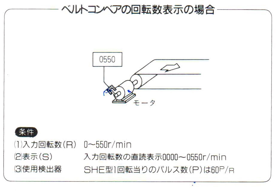
In the case of pump flow display
(1)Input speed (R) 0 ~ 300r / min
(2)Flow indicator (S) 00.00 - 10.00 l / m in
(3)Meter measurement flow display 1 second sampling time (ch) 1.000 (s)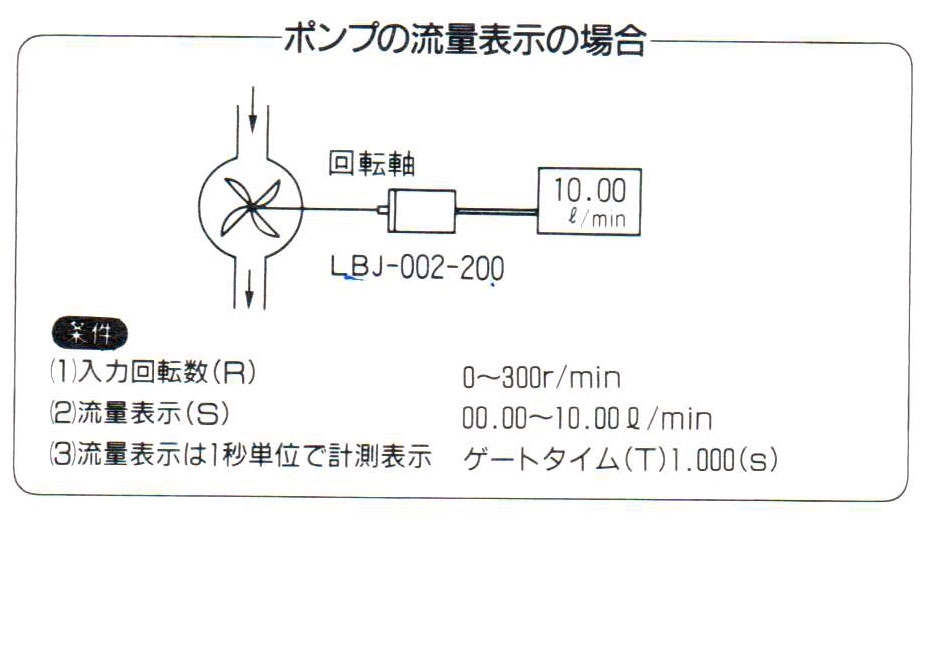
Paper feed speed display
Feed speed 0 ~ 80.00 m / min
Roller diameter O 300.0
Drum speed 0 ~ 84.88r / min
Detection pulse number 600 P / R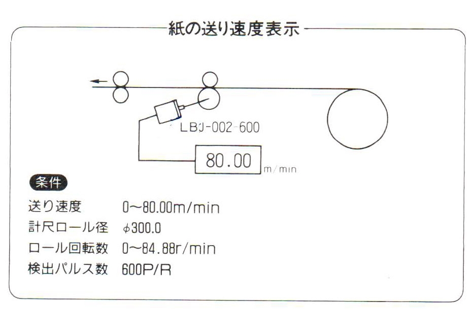
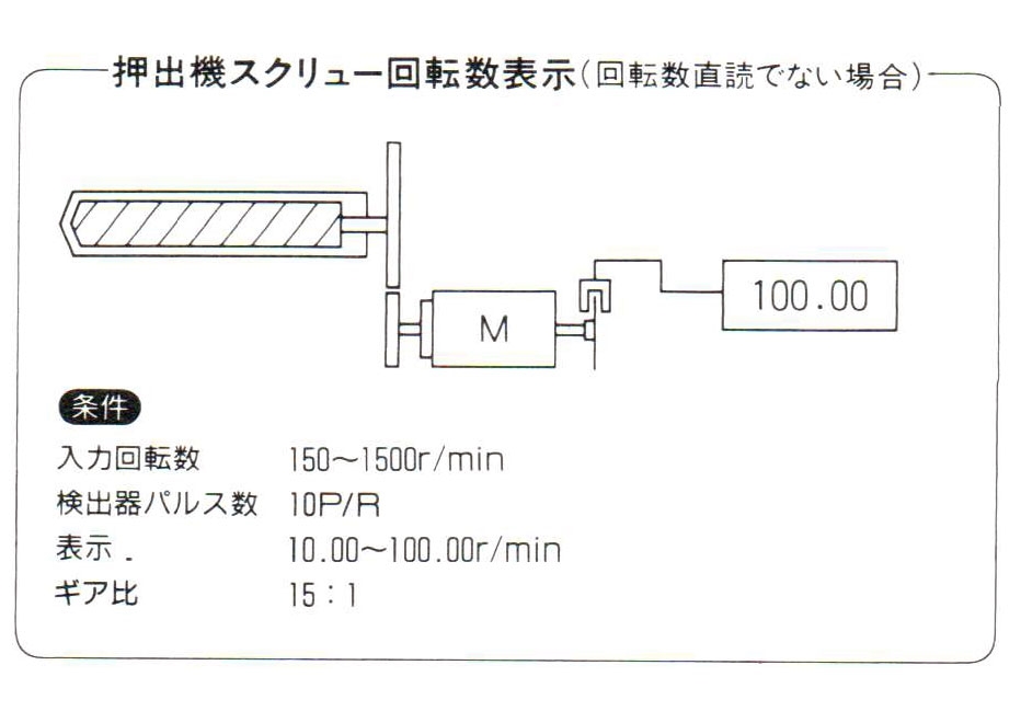
Extruder number display speed (direct speed)
Input speed 150 ~ 1500 r / min
Detector pulse number 10P / R
That 10.00 ~ 100.00 r / min
Gear ratio 15: 1
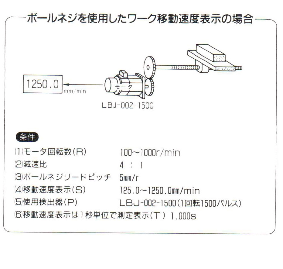
Use the ball screw to show the movement speed of the job
(1)Motor speed (R) 100 - 1000 r / min
(2)Reduction ratio 4: I
(3)Ball screw lead 5mm / r
(4)Movement speed display (S) 125.0 ~ 1250.0mm / min
(5)Using Encoder (P) LBJ - 002 - 1500 (1 RPM 1500)
(6)Movement speed display Displayed in 1 second (T) Measurement 1.000 seconds
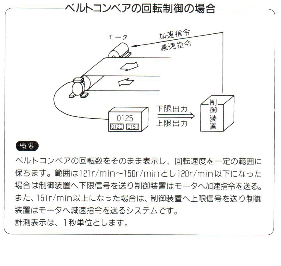
Conveyor speed control occasions
Belt conveyor speed is displayed as it is, speed set within a certain range
I will keep the range of 121 r / min ~ 150 r / min less than 120 r / min
If yes, send the lower limit signal to the control unit to the motor
Send acceleration instruction.
In addition, when it exceeds 151 r / min, the upper limit signal is transmitted to the control device and is executed
The control unit sends a deceleration command to the motor.
The indicator shows for 1 second.
-
HEIDENHAIN / SUMTAK Encoder product model listHEIDENHAIN / SUMTAK / Encoder product model list[ PDF file ]
-
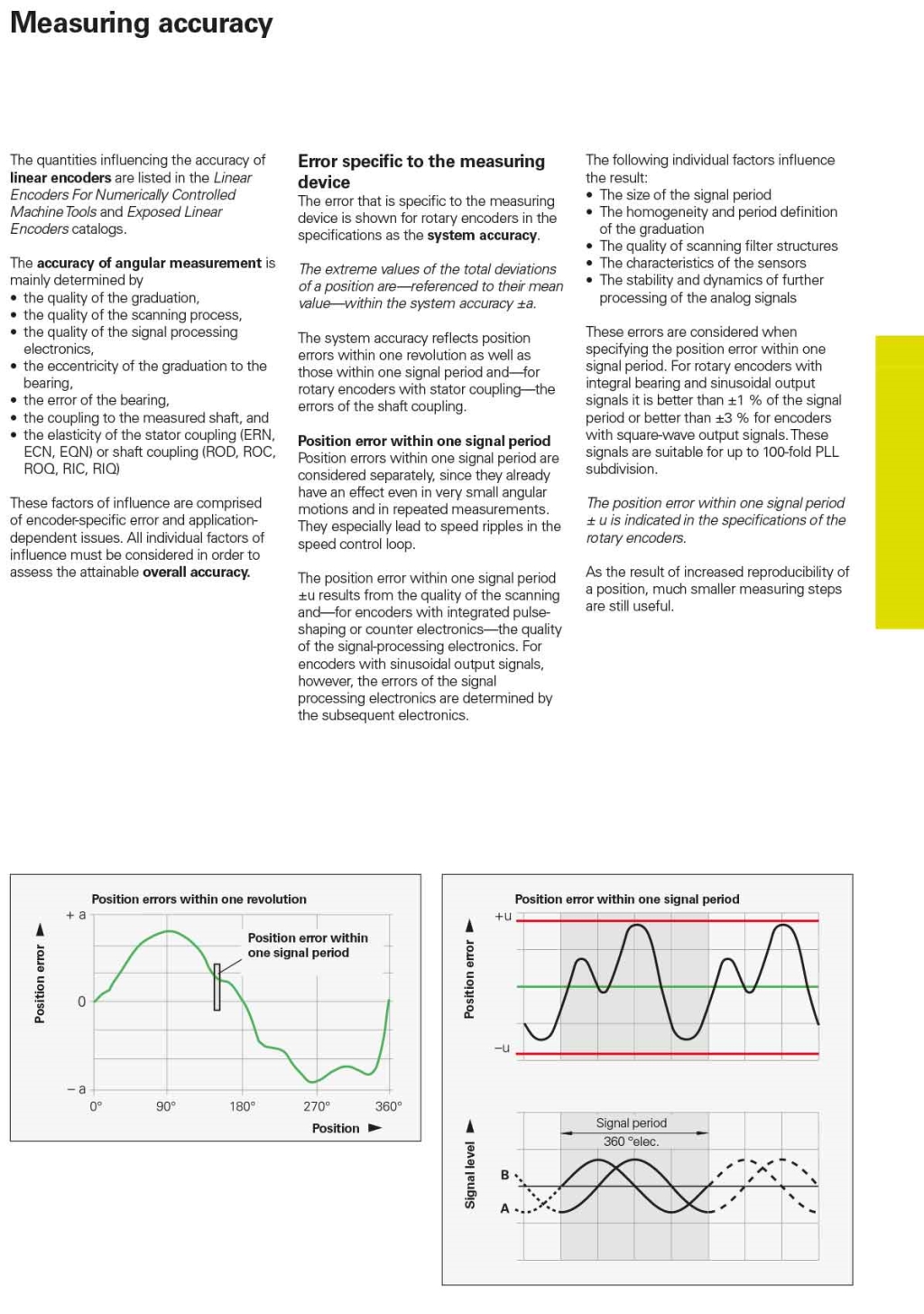
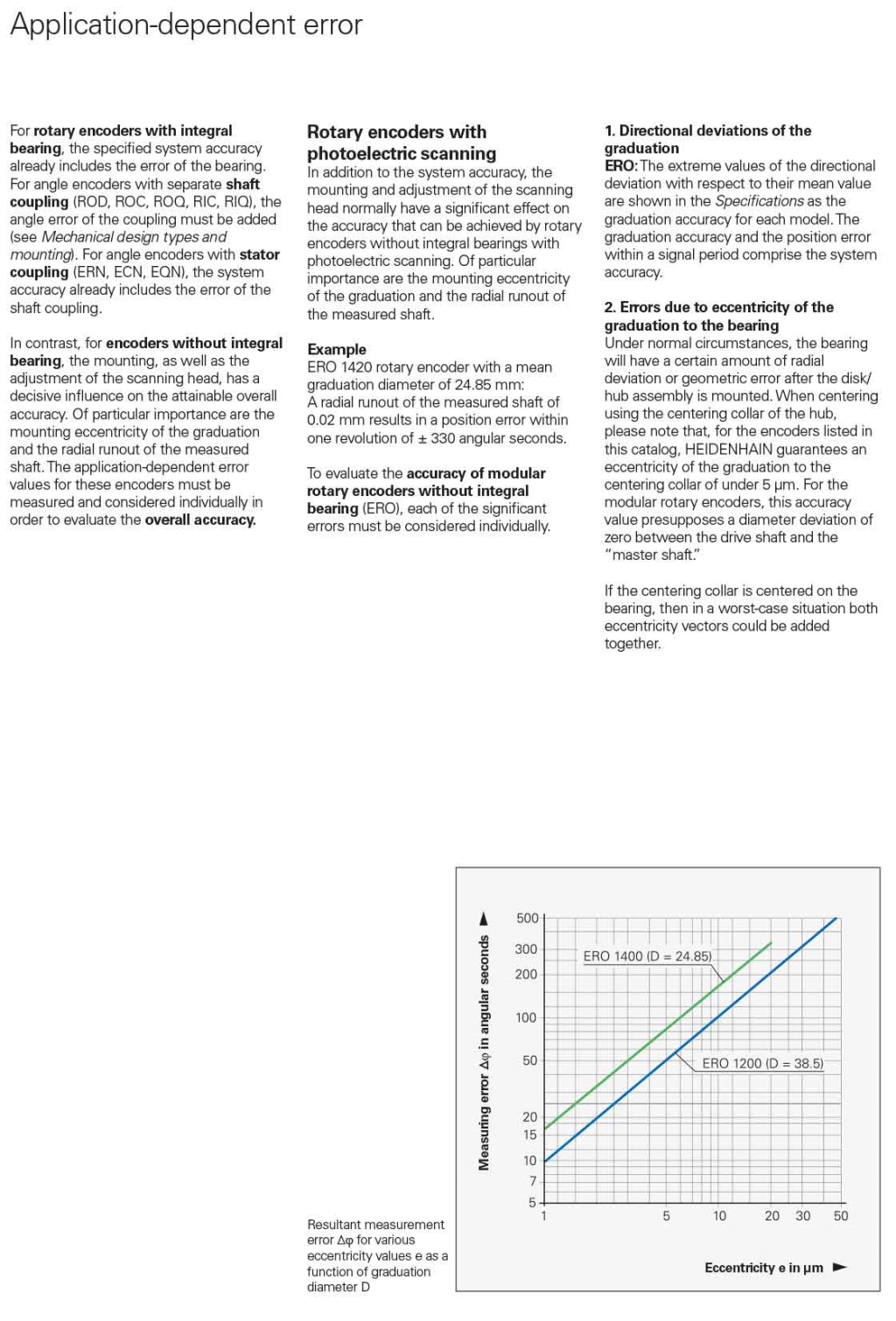
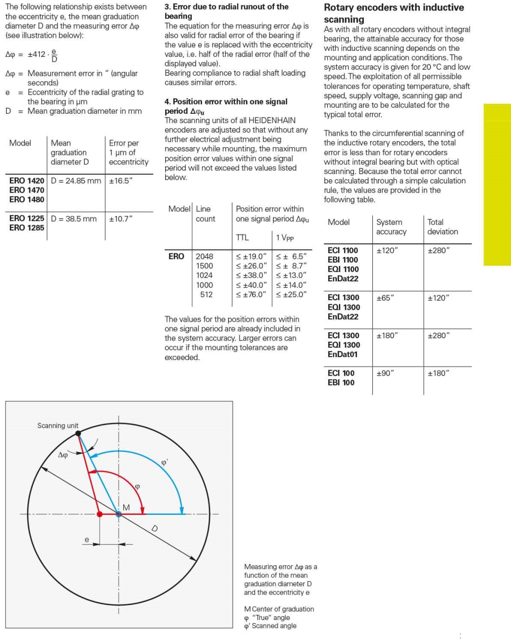
Measuring accuracy of Rotary Encoders
